Note that H-baffle, etc., resonances can be excited by harmonic distortion products - of which there will no doubt be plenty!
It seems that problem solved, question answered.
I am not at home so cannot do any experiment/measurement, but I am really interested did +6dB coming from so called virtual baffle effect or from pronounced 8 pattern and higher beaming what I would prefer
I am not at home so cannot do any experiment/measurement, but I am really interested did +6dB coming from so called virtual baffle effect or from pronounced 8 pattern and higher beaming what I would prefer
Next pic comes from Tim Mellow, at Rudolf Finkes's homepage Dipolplus - Alles über offene Schallwände

Just wanted to point out that this pic compares two models of a dipole:
Zwei Punktquellen mit Abstand D = two point sources with separation D
Zwei Punktquellen aud Kreisscheibe mit Radius D = two point sources on a disc of radius D
Neither one of these responses is of a compound dipole.
SL's four-point-source model of the compound dipole is only valid at low frequencies. At higher frequencies the membrane surface is no longer "point like" and so it's necessary to measure the responses on and off axis to know what is going on for sure. The cone shape, basket design, and motor size/shape can all influence the dipole response at higher frequency (especially to the rear), so I would not be surprised to see the same for the compound dipole.
Note that H-baffle, etc., resonances can be excited by harmonic distortion products - of which there will no doubt be plenty!
True, but practically speaking this is true only for high Q resonances and that is typically not the case in H-frames except for extremely compact Ripole-type designs.
Is anyone in a position to be able to attach an accelerometer to one (or both) cones, and see if there's any difference in excursion between 1 driver and 2 tandem drivers?
I've sort of assumed that excursion will be very similar, being mostly defined by cone mass, but this may not be the case.
I've sort of assumed that excursion will be very similar, being mostly defined by cone mass, but this may not be the case.
keithj01 :
The cone excursion will be determined by the input power. The driver is essentially operating in "free air" and so the TS parameters determine everything about the operation near resonance. There is no need to measure. It can be calculated very easily and is deterministic. One driver (of the same model) will be just like the next one. It doesn't matter how many are operating in a room, near or far from each other.
The cone excursion will be determined by the input power. The driver is essentially operating in "free air" and so the TS parameters determine everything about the operation near resonance. There is no need to measure. It can be calculated very easily and is deterministic. One driver (of the same model) will be just like the next one. It doesn't matter how many are operating in a room, near or far from each other.
Obviously the excursion is dependent on input power, but it's possible that the air load is sufficient to affect excursion more than the small amount you'd expect from the mass of air being displaced.
For instance, contributor Bill F states the following in the Legacy Whisper Bass thread (about tandem drivers): "I believe their close spacing also serves to raise their Qts, since half the airload damping is effectively removed from each cone.".
For instance, contributor Bill F states the following in the Legacy Whisper Bass thread (about tandem drivers): "I believe their close spacing also serves to raise their Qts, since half the airload damping is effectively removed from each cone.".
If there is a change in Qts for the drivers in a compound dipole you should be able to measure it using e.g. a Woofer Tester or other electronics that can do TS parameter measurements. You could (for example) place the drivers facing the same way and side-by-side from each other, measure the TS parameters, and then move them into the compound dipole arrangement and re-measure.
That would be a lot easier than using an accelerometer!
That would be a lot easier than using an accelerometer!
Last edited:
I discovered this thread today. Very interesting! After reading through it, I decided to redesign my Deltalite + Heil AMT minimal baffle project for suspended mounting. And the bass solution would fit as well (I was not decided yet on what to use for bass).
First of all, I really like the look of this system bushmeister. I have always wanted to try dipoles but never had enough space to do so. Your system REALLY makes me crave more space!
Pretty interesting situation this compound bass section. I would have guessed no increase in output at all. Clearly not the case.
I crave seeing nearfield measurements, ~0.5cm from the cone, to eliminate the room from these typical messy in-room measurements. May also be interesting to shoot a measurement in-between the compound woofers. Like exactly in-between. Wouldn't we expect to see zero spl there? If zero spl there then how does this produce more spl on either side?!?!? Very curious thing this...
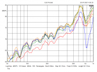
I wanted to explore the nude clamshell arrangement a bit more to figure out what was going on so I did some measurements. It's cold out today so I scaled down the size of my test rig so I could do it indoors. Drivers were 15W/8530K01 There was always the magnet of one driver facing the mic. Its mounting flange was 500mm from the microphone.
First plot is a single driver (Red), two drivers with ~2mm surround spacing (Grey), 25mm spacing (Green), 50mm spacing (Yellow), 100mm spacing (Orange) and 200mm spacing (Blue)

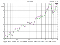
This next plot shows the two drivers with a 25mm spacing (Green) vs the same with the chassis taped together to seal them up, effectively puting them in a tube (Violet).

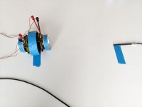
Here is the test setup for the second plot:

The plot with the drivers sealed in a tube vs nude suggests to me this arrangement is behaving as though there is a slug of air simply moving back and forth between the two drivers, when they are mounted reasonably close together, not two different to b. in this image:
The top plot also suggests this is true up until it all falls apart around when the spacing aproaches the chassis diameter.
First plot is a single driver (Red), two drivers with ~2mm surround spacing (Grey), 25mm spacing (Green), 50mm spacing (Yellow), 100mm spacing (Orange) and 200mm spacing (Blue)
This next plot shows the two drivers with a 25mm spacing (Green) vs the same with the chassis taped together to seal them up, effectively puting them in a tube (Violet).
Here is the test setup for the second plot:
The plot with the drivers sealed in a tube vs nude suggests to me this arrangement is behaving as though there is a slug of air simply moving back and forth between the two drivers, when they are mounted reasonably close together, not two different to b. in this image:
The top plot also suggests this is true up until it all falls apart around when the spacing aproaches the chassis diameter.
Attachments
Last edited:
Thank you Andrew, seems like I must turn around and keep on progressing....
But how was electric connection done? Anyway the effect of separation distance is very interesting
But how was electric connection done? Anyway the effect of separation distance is very interesting
OK, trying to get my head around these really interesting results - so it is great you have confirmed and validated my measurements - with the 6dB rise in output with this configuration versus a single driver.
But how do we explain the similar results with the sealed isobaric configuration?
But how do we explain the similar results with the sealed isobaric configuration?
Last edited:
Apologies - on my phone at the moment - so didn't have a great view of your graph scaling.
Hold on - so you have only gained 3.5-4.0dB?
Did you use two separate amps - i.e. double the power?
Hold on - so you have only gained 3.5-4.0dB?
Did you use two separate amps - i.e. double the power?
Last edited:
My second thought is - the difference in your outputs apart from the grey measurement (2mm separation) are all actually not that different given your scaling, and therefore could be explained by a change in the acoustic source distance from the mike - given you are measuring only 50cm from the mounting flange of the front woofer?
- Home
- Loudspeakers
- Multi-Way
- The 'Circles of Doom’... Open baffleless full range speakers