No no not at all;
V1 with V- greater than -21V it is better even.
the power supply winding I have for the buffer is a 21V winding, gives 27V after rectification. But if I put the buffer at -7 volt, with the existing power supply, will give the 2SK170 7+21V=28Vd and the lower one, -21-7V=-14Vd. So I reduced the positve supply a bit (as far as I could go in my potmeter) to a Vd of +19V.
Why? In practice, the one of the fets evidently has gate current (around 225.2252252 10^-9 amp I could not resist posting this nice mathematical outcome), and the output deviates (because of the 220K) by 50 mV @ +/-21V; reduced it is now, otherwise 5mV, --> of course 100K would be OK too.
triode_al, I have a question about the meters i- mine they are FAR FROM accurate, not usable at all...
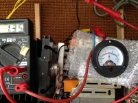
I bought DC-ampere meters.
Might it be that you bought AC-ammeters? That will not work in the DC line, probably only in the output, being AC there . . and not accurate for the power;
For instance I just connected my 32 ohms headphone on the amp - marvelous . It is louder, because the internal Rdrain (like the plate impedance) is about 15 ohms.
Last edited:
I have it indeed before the choke, could put it also before the TIP142 by the way but I'll probably fool around a bit with the power supply - bigger 0,6 ohm choke to go in and one central CM/slow-starter if still required. [I heard a persistant 100 Hz hum residue on the headphone]
- Your question makes me a bit unzen, I expected the meter is just a shunt resistance which is flat i.e. not very inductive and hence have no impact, because its value is swamped by the big 'power line' choke I have. But seeing I have 1 mm thick drain wires & 2mm source-earth wires I use - it can count.
- Your question makes me a bit unzen, I expected the meter is just a shunt resistance which is flat i.e. not very inductive and hence have no impact, because its value is swamped by the big 'power line' choke I have. But seeing I have 1 mm thick drain wires & 2mm source-earth wires I use - it can count.
Last edited:
proper way is to use that sort of meter as regular mV meter - either having proper "shuntless" one, or get rid of internal shunt if there is any
then tap to appropriate points in circuit and take fraction of available voltage to route to meter
I was recently explaining that , in some thread , to peppennino, I believe
amplifier is not damn pre-war Norton or BSA, to have in-line A-meter
then tap to appropriate points in circuit and take fraction of available voltage to route to meter
I was recently explaining that , in some thread , to peppennino, I believe
amplifier is not damn pre-war Norton or BSA, to have in-line A-meter
I see, I'll check the shunt value
I like the comforting analog indication it gives. Should have a little real bulb behind it. It gives me piece of mind.
Anyway I am thinking to go to an CrC anyway, the R being 0,1 ohm. 🙂 But I can't open the meter up, I'm afraid it will self-destroy.
I like the comforting analog indication it gives. Should have a little real bulb behind it. It gives me piece of mind.
(might be 0,1 ohm, that would be too high . . . when I take all the effort to have a low Rdc choke of <0,5 ohm)
My old Zündapp had a starter motor as dynamo (hybrid as we call it now) and that had a nice dual range meter, maybe something like this

Anyway I am thinking to go to an CrC anyway, the R being 0,1 ohm. 🙂 But I can't open the meter up, I'm afraid it will self-destroy.
I bought DC-ampere meters. Might it be that you bought AC-ammeters?
no no, mine is DC ammeters. I double checked mine, and I find they look different from yours. I bought mine for less than $5 each... Cheap meters. Thank you anyway. 🙂
you really don't know better than to put meter inline with circuit?
I bought tiny LCD digital voltmeters and 0.1% resistors instead. I only turn on the voltmeters when I need to see them. Is this a good idea?
I have no objection

same as I'm not having nothing against use of in-line Ameters in CRC filter .... thougg, care needed in powering On sequence, to avoid needle bang
same as I'm not having nothing against use of in-line Ameters in CRC filter .... thougg, care needed in powering On sequence, to avoid needle bang
triode_al,
Congratulations, a solid state amp that is competitive with a 300B amp (or better)! 😀
Congratulations, a solid state amp that is competitive with a 300B amp (or better)! 😀
I have no objection
same as I'm not having nothing against use of in-line Ameters in CRC filter .... thougg, care needed in powering On sequence, to avoid needle bang
Thank you, ZM. 🙂
triode_al,
Congratulations, a solid state amp that is competitive with a 300B amp (or better)! 😀
Thanks. Of course the 300B has a lot of merits but is such a fussy girlfriend. I have Tent-regulators, my anode shows no hum nor noise, not even 1 mV. I do need a source follower for the driver and the tube will never go below Va 50 or so (does not go to 5 volts like for instance a 10Y), and you might be listening to the driver stage as some say. My 300B gives a very nice stage and harmonics on a Lowther or my Fostex.
Still this CH'AMP I have now surpasses it - in overall rendition, harmonics. Because the lower end is stronger I think. The stage is different - I do have the polarities inversed right now; it is briljant.
When I had my Lowther I always tuned for the stage folding backward, but that was very tricky, depended so much on my Meridian 206 that allows that 'trick', giving meters of depth. But at a certain moment that stage started to confuse me, isn't it artificial?
Now I think I have found what I was looking for.Next I think maybe I'll transform my ACA into an AKAsit {by coincidence, AKA is my company name, have logo . . .}
Attachments

I finally started work on my build of this project over the weekend. Started cutting and drilling the metal work for the chassis and designing a small PCB to keep things eat and tidy. I'll post some pictures when I've made a bit more progress.
My pair of TH-51s are destined for a SissySIT build so this will now be using 2SK180s.
A numpty question if I may - do I need a negative bias per supply per channel or will a single one suffice?
My pair of TH-51s are destined for a SissySIT build so this will now be using 2SK180s.
A numpty question if I may - do I need a negative bias per supply per channel or will a single one suffice?
Last edited:
do I need a negative bias per supply per channel
The bias supply will need to be adjusted separately for each channel, so as long as you have individual pots, decoupling caps and series resistors per channel you can use a common transformer, rectifier and regulator.
Thanks analog_sa.
Yes, I'll have seperate adjustment of the bias for each channel so a single supply should work. I ask because I'll probably use Mark Johnson's power up module
PCB: low voltage On-Off switch drives AC mains relay \ includes soft start .. H9KPXG
which has an auxillary 5V supply available. Perhaps -5V might not be enough for biasing but I could probably use a 12V supply for the module with some component changes - I'll check out the thread.
Alternatively, instead of a conventional CRC power supply I may use one of these
SMPS800RS | Connex Electronic
Last edited:
Slightly off topic perhaps, but (thinking about running a cooling fan at half-speed) I came across these the other day: QitinDasen 7Pcs Premium LM2596 DC to DC Buck Converter, 3.2~40V to 1.25~35V Adjustable Buck Module, 3A Power Supply Voltage Regulator : Amazon.co.uk: DIY & Tools
Has anyone explored their limitations?
(Forgive my ignorance if they should be obvious - my limited technical knowledge is not so much accelerating as gathering momentum )
)
Has anyone explored their limitations?
(Forgive my ignorance if they should be obvious - my limited technical knowledge is not so much accelerating as gathering momentum
)A buddy of mine looked at something very similar in an non-audio application, but found the output too noisy.
I suggested running the output through Mark Johnson's PO89ZB_A_SMPS_Inline_Filter....which made them usable.
I suggested running the output through Mark Johnson's PO89ZB_A_SMPS_Inline_Filter....which made them usable.
Slightly off topic perhaps, but (thinking about running a cooling fan at half-speed) I came across these the other day: QitinDasen 7Pcs Premium LM2596 DC to DC Buck Converter, 3.2~40V to 1.25~35V Adjustable Buck Module, 3A Power Supply Voltage Regulator : Amazon.co.uk: DIY & Tools
Has anyone explored their limitations?
(Forgive my ignorance if they should be obvious - my limited technical knowledge is not so much accelerating as gathering momentum
- Home
- Amplifiers
- Pass Labs
- 25W Single Ended Hammond 193V Choke Loaded 2SK180 L'Amp