Can I see the schematic?
I'm not ready to share it. But you can look my other design that use similar topology: Slewmaster - CFA vs. VFA "Rumble"
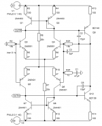
I don't get it. I added a VAS and I cannot get the CM to misbehave. Even when ramping up the PSUs:

Using 2N5401/5551 doesn't make any difference. I fail to see how the LTPs fight each other. What am I overlooking?
Using 2N5401/5551 doesn't make any difference. I fail to see how the LTPs fight each other. What am I overlooking?
Attachments
My sim doesn't seem to need them. What would be the point? Why does the Real Life LTP refuse to start up properly but the sim works just fine? Or rather, how can I get the sim to misbehave?As in previous schematic, you need 47-100K resistors between Q3-Q4 and Q5-Q6 collectors.
Edit: Cordell makes some interesting remarks about this issue in his book (page 137).
Last edited:
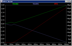
Wait a minute... the LTP is not the problem, the quiescent current in the VAS is. I was put off by the schematic of only the LTP. The sim shows this just fine: the current is only 0.4 mA. Way too low for a VAS.
In the real world the current might not even be 0.4 mA. It could refuse to start up, or jump to a high value causing overdissipation.
Well, it helps to actually read what is written instead of diving right in. Guess I'm getting too old for this sh*t...
Edit: this is a well-known movie quote. Censored?!?!?
Edit: this is a well-known movie quote. Censored?!?!?
Wait a minute... the LTP is not the problem, the quiescent current in the VAS is. I was put off by the schematic of only the LTP. The sim shows this just fine: the current is only 0.4 mA. Way too low for a VAS.
The last sim I posted shows VAS collector current of 3.6mA.
As in previous schematic, you need 47-100K resistors between Q3-Q4 and Q5-Q6 collectors.
Doesnt this just defeat the point of having the current mirrors?
Doesnt this just defeat the point of having the current mirrors?
I'd like to know how they wouldn't function as mirrors to begin with. Was 47k added to balance them? Could they be so far out of balance that the VAS has no base current? Wouldn't that initial imbalance put a large DC offset at the output? Wouldn't the LTP then put that back in balance?
Doesnt this just defeat the point of having the current mirrors?
A little bit. Better than only use resistor but worse than only use current mirror.
Because if you use high value resistor, the current of LTP must be low, then the slew rate is low, too.
That shows the issue with your CM. A magnitude difference in VAS bias current compared to my sim. Note that you cannot properly control this current with your CM as Bob Cordell pointed out in his excellent tome. Quick fix: use resistors...The last sim I posted shows VAS collector current of 3.6mA.
Suppose you want a VAS current of 10mA and the VAS transistors have a Beta of 100. That means the Diff-amps have to provide 100uA to the bases from the positive sides of the LTPs. But there is no mechanism that creates that current difference in both LTP at the same time. The NPN LTP needs a slight negative offset and the PNP LTP needs a slight positive offset to provide 100uA outputs to the VASs. Normally the DC offset adjusts until the VAS current matches the current source opposite the VAS. But here the DC offset reduces one VAS current while it increases the other but there is no mechanism that adjusts the total /average. Resistor loading works because the VAS emitter resistor drop plus the VAS VBE adds up to the LTP current times the loading resistor. In simulation, transistors always match perfectly, but that doesn't happen in real life. You could use a POT instead of one set of LTP degeneration resistors to adjust one LPT offset to match the other. You could use that POT instead of in the usual idle current VBE multiplier POT. Adding resistors to the current mirrors creates an offset that feeds the VAS base currents.
This is similar to the reason you can't parallel two op-amps without resistors to separate the two outputs. They are rarely exactly the same temperature and offset etc so there will always be a few uV difference that they will fight over, except in a theoretical simulation. The resistors limit how much current it takes for both to have their own way.
This is similar to the reason you can't parallel two op-amps without resistors to separate the two outputs. They are rarely exactly the same temperature and offset etc so there will always be a few uV difference that they will fight over, except in a theoretical simulation. The resistors limit how much current it takes for both to have their own way.
Last edited:
I concur. You must define the operating point of the VAS. Bob Cordell needs a lot of extra components to accomplish that. You want to keep the number of adjusting elements (pots) to an absolute minimum at the expense of using more silicon.
And now for something (not really) completely different.
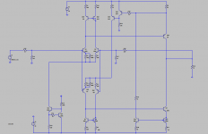
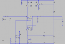
Attached is a symmetric IPS where the VAS current is regulated. The two VAS currents are summed and control the current constant for one of the LTPs. Both LTP have a deliberate offset that increases the positive side of the LTP to provide the VAS base currents.
Attached is a symmetric IPS where the VAS current is regulated. The two VAS currents are summed and control the current constant for one of the LTPs. Both LTP have a deliberate offset that increases the positive side of the LTP to provide the VAS base currents.
Attachments
Some tweaks:
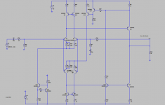
Some tweaks. We can mirror the lower VAS more efficiently. And I tweaked the offset and added DC blocking caps.
Some tweaks. We can mirror the lower VAS more efficiently. And I tweaked the offset and added DC blocking caps.
Attachments
Last edited:
- Home
- Amplifiers
- Solid State
- Trouble with HEXFETS