I just "accidentally" ordered two rather phat toroid transformers from a surplus dealers. The more realistic option is to use them in a power supply for my almost-finished class A SS amp but I couldn´t help noticing their potential use as PP OPT´s with CFB windings.
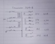
Assuming a symmetrical 115+115V primary we should have a winding ratio of (115+115+37+37)/19 = 16, ignoring the low current 18 and 27V windings.
16^2*8 =2048 Ohms Ra-a, right in the ballpark for a pair of EL509 or maybe a quartet of smaller sweep tubes.
Worth a try, or should I put them in my SS amp right away?
The combination of big sweep tubes and a PP CFB topology would probably attract some interest from the God of Oscillating Amplifiers...and possibly from George at Tubelab too
Attachments
Time for some serious breadboarding again, it's been a while since last.
The primary inductance is probably rather low in these transformers (250VA estimated) but that 37-0-37V winding should be helpful in that matter. (230+37+37)/230= 1,322, so 32% more turns which should result in 1,322^2 = almost 75% more inductance.
The primary inductance is probably rather low in these transformers (250VA estimated) but that 37-0-37V winding should be helpful in that matter. (230+37+37)/230= 1,322, so 32% more turns which should result in 1,322^2 = almost 75% more inductance.
Core materials for a power type and other types of transformer (xfmr) are different, so even if turns ratios on a power xfmr are okay for output xfmr use, the core characteristics (how fat is that hysteresis loop?) of a power type xfmr could limit the performance in audio (wideband) settings. Best thing to so is just try the transformer and give it a listen after some preliminary testing to see if it's even in the running.
The primary inductance is probably rather low in these transformers (250VA estimated) but that 37-0-37V winding should be helpful in that matter. (230+37+37)/230= 1,322, so 32% more turns which should result in 1,322^2 = almost 75% more inductance.
Probably good for around 18-20W into 2k a-a load at 30 Hz.
That's the plan. The transformers were quite cheap but the shipping was not, I would'nt have bought them without a plan B to use them in a power supply.
At least it will be an interesting experiment and, hypothetically, if they work well down to 35Hz but not all the way up to 20k I may have use for them anyway: My front loaded bass horns only covers 35-80hz
At least it will be an interesting experiment and, hypothetically, if they work well down to 35Hz but not all the way up to 20k I may have use for them anyway: My front loaded bass horns only covers 35-80hz
Yes, the hysteresis loop is wider than for a true AF transformer, which explains the low apparent inductance.
The simplest way to determine the amplitude inductance, which will determine the actual bass capability, is to measure the no-load current with the regular 230V/50Hz input, derive the reactance and finally the inductance.
The high hysteresis will also cause significant distortion for topologies having a high output impedance and low or zero feedback.
With feedback or a CF topology, this shouldn't be too much of a problem.
The arrangement of the windings will also cause problems: HF rolloff due to the leakage inductance (but relatively benign for a toroid) and high/unbalanced parasitic capacitances.
It is worth testing anyway: you could be pleasantly surprised (or not...)
It is an approximately 250 watt transformer.
Some things to note:
- core excitation, being a power supply transformer, will be something like 1.6 - 1.8 T, while a typical quality output transformer would not go over 1 T.
This transformer will have a severe constraint in power being used as EL509 output transformer;
- the transformer is designed for 50/60 Hz; for audio we need good performance down to 20-25 Hz, so an octave lower which normally requires two times more power from the core;
- primary induction will be lowish, forcing the core into saturation quickly.
My suggestion: not suited for EL509, but an option might be 6AS7/6080 PP (also not so critcal for HF loss as this tube is low Rp).
Last edited:
I see now that I should have been more specific in my first post: EL509 was the first tube that popped up in my mind, but I never mentioned that I visualized them running as triodes* and in class A. I don't have much use for 100W+ amps in my horn rig
* Wiring them as triodes might not be the only option. Fixed G2 voltage and cathode feedback actually sums up to Ultralinear operation, for better or worse... This would be similar to the output stage in Quad II. True pentode operation would be a bit more complex as the screen grids would have to "move" along with the cathodes.
* Wiring them as triodes might not be the only option. Fixed G2 voltage and cathode feedback actually sums up to Ultralinear operation, for better or worse... This would be similar to the output stage in Quad II. True pentode operation would be a bit more complex as the screen grids would have to "move" along with the cathodes.
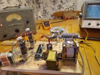
The transformers arrived today and just ran some initial tests with rather interesting results:
Pretty much flat from 20Hz to 30k, with a resonance peak around 40khz.
At 1,5W though, as I run the tubes wired as triodes and at low voltage/current (120V 50mA) for now.
Phase splitting is done with an LL1660 which may or may not introduce some extra flavor to the frequency response.
Pretty much flat from 20Hz to 30k, with a resonance peak around 40khz.
At 1,5W though, as I run the tubes wired as triodes and at low voltage/current (120V 50mA) for now.
Phase splitting is done with an LL1660 which may or may not introduce some extra flavor to the frequency response.
Attachments
Update:
Seems like the LL1660 is guilty of much of the HF mischief. An LTP phase splitter would probably be a better choice while evaluating the OPT.
A better power supply must also be built for further testing, I ran out of juice at 255V (minus a 28V drop across the cathode resistors) and 140V for the screen grids which resulted in 20W into 7.5R.
You should measure primary inductance and leakage inductance , than we will know what can be done with them .
My 15 dollar LCR meter says 1,25H across the primary winding, CFB winding not included. This doesn´t add up well with the fact that I still have almost full response at 15Hz? I don´t trust my LCR meter much when it comes to large iron cored inductors.
Leakage inductance is measured with a shorted secondary winding, am I right?
Yes, short all the secondaries to measure the global, primary-referred leakageYes, the hysteresis loop is wider than for a true AF transformer, which explains the low apparent inductance.
The simplest way to determine the amplitude inductance, which will determine the actual bass capability, is to measure the no-load current with the regular 230V/50Hz input, derive the reactance and finally the inductance.
- Home
- Amplifiers
- Tubes / Valves
- Surplus toroid transformers as OPTs...with a little twist.