Please use the Telefunken schematic for correct grounding and the Korean schematic for understanding inputs and outputs.
Advice: please use better quality cabling and put the wire through the holes at the outside (you will notice the internal wires to be soldered to the inside holes/lugs and you don’t want these to disconnect). Then solder with 60/40 solder. Don’t leave too long bare copper wire but make it tidy. Also make sure to do stuff good at once as you don’t want to resolder these too much.
It would also help if you could mention the exact type you have and to do the howework by correcting the relabeled terms to the original ones. That helps us and yourself.
Last edited:
Well, thanks very much to all of you that help me with this. Today I connected the transformers in this way and they work but there are two options. In option B it sounds louder than A. I dident know about that it was possible to get two different options. In the Korean schematic they do a connection to "LO and HIGH" options with a switch but i havent dont anything like that.
What do you think?.
What do you think?.
Attachments
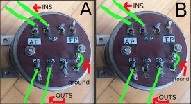
Then you missed to see that there are 2 different output windings but you found out you have 2 possibilities so in fact you did find out 🙂
Do NOT connect Shield directly to the Chassis pin/bolt as extensively shown in the Telefunken schematic. Think of the chassis being connect to PE (safety!) and Audio GND to be a separate item. Chassis should not be part of the circuit in good audio.
Do NOT connect Shield directly to the Chassis pin/bolt as extensively shown in the Telefunken schematic. Think of the chassis being connect to PE (safety!) and Audio GND to be a separate item. Chassis should not be part of the circuit in good audio.
Last edited:
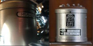
The sound in option B has more gain and at the same time I can hear the transformer more, its very subtle because is very transparent but its there. Here on more pic of the front and beside there is other info. What i was not expecting is this different because ratio is 0,7: 1 and in option B is something like 5dbs.
Attachments
Yes because the transformers have 2 output windings so you can have 2 different transformation ratios. When the 2 output windings are used in series or when just 1 of the windings is used you will have 2 different impedances and ratios. In layman's terms there will be a LO and HI output. The letters P are used for Primary and the S for Secondary but I think the transformers are often used in reverse.
What we need now for correct understanding is either specifications or a datasheet of the E5-M type. Please reread this thread again and check the Korean schematic for the principle of the 2 windings.
* I edited my posts as I now think there are even 2 input and 2 output windings on the E5-M type so you have quite some possibilities.
Last edited:
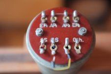
The picture of post 27 would have been useful to see from the beginning to prevent endless speculation.
Yes because the transformers have 2 output windings so you can have 2 different transformation ratios. When the 2 output windings are used in series or when just 1 of the windings is used you will have 2 different impedances and ratios. In layman's terms there will be a LO and HI output. The letters P are used for Primary and the S for Secondary but I think the transformers are often used in reverse.
What we need now for correct understanding is either specifications or a datasheet of the E5-M type. Please reread this thread again and check the Korean schematic for the principle of the 2 windings.
* I edited my posts as I now think there are even 2 input and 2 output windings on the E5-M type so you have quite some possibilities.
THANKS FOR THIS, I APPRECIATE IT A LOT.
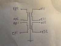
Yes for input it seems that the only way is how is now connected, other options doesnt work. So it seems to be only one option to go in.Here is what I think the E5-M is... I forgot to put the "S" for Schirm/Shield.
Thanks for making it even more complex 🙂 The autoformer option is already shown in the Korean schematic and it means the galvanic separation is lost so not to be preferred.
@fuaelo: please stop resoldering the devices but use small crocodile clips (preferably the least aggressive copper ones) with wires to check all possibilities. I think there are 2 input and 2 output windings. It really does not help if you keep trying out without understanding the difference and if you talk about "other options". This is a technical forum so "other options" should be mentioned in detail or drawn on a schematic. If you want correct help then please deliver usable data.
We would be helped if an other E5-M owner would see this thread to confirm. You can also wire the transformers in a metal casing and use switches for all settings to make it a versatile device. If my assumptions are true then there are a lot of different transformation/impedance/gain possibilities. Or you use the technical approach and think beforehand what exactly is needed in terms of gain/impedances/transformation ratio.
Please reread the thread on all advices and tips and try to understand what 2 input windings and 2 output windings exactly mean and what they can do.
Last edited:
Thanks for making it even more complex 🙂
@fuaelo: please use small crocodile clips with wires to check all possibilities. I think there are 2 input and 2 output windings. It really does not help if you keep trying out without understanding the difference.
We would be helped if an other E5-M owner would see this thread to confirm. Do not resolver the e5-M various times but experiment with crocodile clips and then wire the transformers and build them into a metal casing. You can also wire the transformers in a metal casing and use switches for all settings to make it a versatile device.
that is very good idea, thanks.
I hope you see that 2 different windings means that you need to connect them in series or either one of the windings. This counts for bot inputs and outputs.
Check the drawing in post #23. If you fail to connect the interconnection between 2 windings and use the outer connections you will not get any signal 🙂
Check the drawing in post #23. If you fail to connect the interconnection between 2 windings and use the outer connections you will not get any signal 🙂
Last edited:
- Home
- Source & Line
- Analog Line Level
- Help to connect MALOTKI transfomers.