Hello, I've looked online but can't find any info about this ;
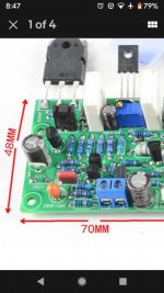
how can I ADJUST BIAS if I can't physically access the emitter resistor* legs ?
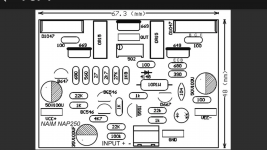
( *White plastic cased vertical resistor in photo )
I am UNABLE to put my digital meter probes onto the legs of the EMITTER RESISTOR as the PCB is so small
Any help greatly appreciated
how can I ADJUST BIAS if I can't physically access the emitter resistor* legs ?
( *White plastic cased vertical resistor in photo )
I am UNABLE to put my digital meter probes onto the legs of the EMITTER RESISTOR as the PCB is so small
Any help greatly appreciated
Attachments
Last edited:
You can measure on the output of the amplifier, and the emitter of the output devices, which are the right leg.
Measure between emitter and emitter on the output pair. Calculate required voltage using ohms law and the combined resistance.
Yes. Measure between the emitters.
But its only of use if you know what to expect and what the correct value should be. Also no load and no signal for the measurement.
But its only of use if you know what to expect and what the correct value should be. Also no load and no signal for the measurement.
Thanks..... The bias data I have is;
Quiescent Current Recommended:
Voltage at both ends of the cement resistor = 1.5 MV-3MV
The current is about 10-20 MA.
So for 20ma of current , I would adjust bias pot until I get a 3mV reading across emitter resistor......
What reading/value would I be looking for when I measure between both transistor emitter legs ?
Sorry if I'm being stupid , but just to be sure ;
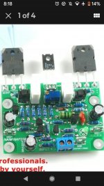
My amp board used 2 x KTD1047 power transistor s
And 1 smaller transistor - 669A
So the emitter to emitter reading , is from D1047 to D1047 ?
I ignore the smaller 669A transistor?
My amp board used 2 x KTD1047 power transistor s
And 1 smaller transistor - 669A
So the emitter to emitter reading , is from D1047 to D1047 ?
I ignore the smaller 669A transistor?
In this case it is a different story. You have to measure across only one emitter resistor. So output transistor emitter and output point is valid. Measure first carefully, with high voltage settings on your measuring device. It it shows 0V, than you can try to set 3mV bias. If it shows high votage (close to the supply votage) you have to measure on the emitter leg of the other 1047.
Last edited:
You have to measure across only one emitter resistor. So output transistor emitter and output point is valid..
Where is the ' output point ' ? ( Is it the 669A transistor emitter)
Last edited:
Output point is where the speaker should be connected.
Thank you .... So I look for the + speaker out , on the PCB ?
I do not actually use the speaker terminal on the amp. Case ?
This is my last question now (!) ... You have helped me so much
Why not just solder two wires to the resistor and bring those out the meter.
As you are so unsure on what you are doing there is a very real risk of you doing something wrong here imo.
As you are so unsure on what you are doing there is a very real risk of you doing something wrong here imo.
Why not just solder two wires to the resistor and bring those out the meter.
As you are so unsure on what you are doing there is a very real risk of you doing something wrong here imo.
It can be complicated, once he has no space to measure, and it can be dangerous if any of that wires touch the heatsink, or the walls of the box.
I agree, he must be very careful, and maybe ask somebody, who is more experienced to do the settings.
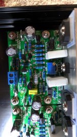
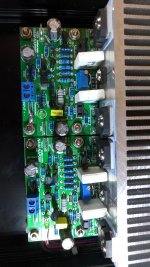
Send a picture, which shows the whole panel. We can show the testpoints.
Photos of amp... Plus schematic I got online ( looks the same board )
--. Do I need to remove the speaker cables from the PCB ( or can I measure with cables connected ?
Why not just solder two wires to the resistor and bring those out the meter.
As you are so unsure on what you are doing there is a very real risk of you doing something wrong here imo.
thanks, thats a good ideal, just means that i would have to remove the PCB from the case ... if i can measure it without having to solder in cables to resistor, well i hope so , 🙂
sorry for delay , had problems with photo uploads....
looks like the positive speaker output is above/next to the trimpot?
all the cables to this board are soldered onto the underside of pcb
Q:- can i take the reading with the speaker + output cable connected? or does it need to be removed to get an accurate reading ? ( the speaker + output goes to a speaker protection circuit )
Attachments
Last edited:
- Home
- Amplifiers
- Solid State
- BIAS - can't access emitter resistor legs