Due to the demand, there won't be any mass email sent for round 2.
However there will be a second entry window quietly advertised in the VFET lottery discussion thread for people who are very keen and following along with the active discussions.
The window date and time will be advertised with at least 3 days notice, in that thread, once we know everything is ready to ship.
Is it still the case that if you were entered for Round 1 you will automatically be entered into Round 2?
It is still the case.
If you would like to be notified about the next window, please go to the lottery discussion thread and follow the instructions in the last post to subscribe to the thread's new post notification emails.
If you would like to be notified about the next window, please go to the lottery discussion thread and follow the instructions in the last post to subscribe to the thread's new post notification emails.
Before the lottery there was a number of posts regarding how many of the P VFET amplifiers would actually be built. With the N VFET about to launch, I thought it would be interesting to see how many are built. Add your name and chassis number if it's playing music:
Elwood625 #28
Elwood625 #28
Please, no counting of the amps playing music. Those who wished to share their experience and ask questions have probably already done so by now. Trying to keep this thread more relevant to the builders and the process.
We know there are about 180 amps of both types (P and N).
We know there are about 180 amps of both types (P and N).
Last edited:
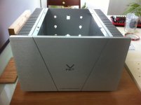
Well, for what it's worth, unit #104 is indeed still making slow progress...
Between another amp build I already had in progress at the time of the lottery (now completed and cleared off the workbench), planning carefully for the mods I want to make (my VFET amp will not be a strict paint-by-numbers build), ordering of parts, and a busy work schedule this past few weeks ... oh, and getting somewhat distracted with a new speaker project in the background ... work on this project has been a bit delayed.
Nevertheless, things are queued up to finally start making some proper headway.
Parts are mostly gathered now ...
Attachments
VFET as a Headphone Amp
A worthwhile experiment to hear how quiet an amp can be performed by connecting headphones to the output of an amplifier. I connected my HE-400i planar magnetic headphones (32ohm) to the output of the VFET and could not hear any noise - it is quiet like a headphone amplifier. Since it is cap coupled, it is quite safe as you don't have to worry about DC offset. It works very well as a powerful headphone amp. The clarity and resolution was quite extraordiarily good. Try it as a headphone amp and you will hear what this amp is capable of in terms of resolving detail. It's a nice way to enjoy your VFET late at night without disturbing others in the house.
A worthwhile experiment to hear how quiet an amp can be performed by connecting headphones to the output of an amplifier. I connected my HE-400i planar magnetic headphones (32ohm) to the output of the VFET and could not hear any noise - it is quiet like a headphone amplifier. Since it is cap coupled, it is quite safe as you don't have to worry about DC offset. It works very well as a powerful headphone amp. The clarity and resolution was quite extraordiarily good. Try it as a headphone amp and you will hear what this amp is capable of in terms of resolving detail. It's a nice way to enjoy your VFET late at night without disturbing others in the house.
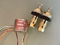
hifiZen, this looks like it’s going to be interesting. Especially when I see a small Cinemag signal transformer in the parts collection.
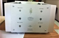
Building a special amp such as this is about the journey as well as the destination. My initial effort on the external linear PSU was in part proof of concept. Next thing is to make it look finished. Gathering some more parts as well..
Building a special amp such as this is about the journey as well as the destination. My initial effort on the external linear PSU was in part proof of concept. Next thing is to make it look finished. Gathering some more parts as well..
Hi guys,
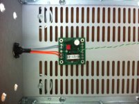
I took this morning some parts at my work in hope to find a break to finalise crimping and the wiring on the filter board. So I haven't got the casing / can't measure anything.
I tend to follow blindly as I did so far all 6L6 advices in the build guide (will be exactly built as intented, same positionning etc.) but I remember there was a discussion about some wires being too short...
Question:
Regarding the grey cables on the filter board, it is said
- 2x « filter to Ground FE », 150mm (6 inches)
- 2x « filter to Ground OS », 200mm (8 inches)
Now I have the exact length left to do just this. But there was a discussion about this cable being too short, someone even advising to rather cut a set (both Ground and +V to OS, so say Grey and Red) for one of the OS boards to 6 inches and a set to 8 inches for the second OS board.
Question is: can I safely follow the guide here and cut exactly as recommended, or do I need to wait until home, do some blank mounting and find out the exact length to be cut for the grey cables?
Would be pity to waste these cable by cutting without double checking, which I do now relying on you, hoping you remember if the recommended length is OK 🙂
Many thanks for your kind help
Claude
Last edited:
The safest thing is to wait until you have your chassis, then do a trial fit with the wiring.
I just ordered some silicone insulated wire to finish the umbilical between my external PSU and the amp. I also got a kit of PTFE insulated wire in several colors to have for this amp as well as future ones.
I just ordered some silicone insulated wire to finish the umbilical between my external PSU and the amp. I also got a kit of PTFE insulated wire in several colors to have for this amp as well as future ones.
With the boards not being mirror imaged I ended up using the 2x6" wires for one channel and the 2x8" ones for the other channel.
...Question is: can I safely follow the guide here and cut exactly as recommended, or do I need to wait until home, do some blank mounting and find out the exact length to be cut for the grey cables
With the boards not being mirror imaged I ended up using the 2x6" wires for one channel and the 2x8" ones for the other channel.
Cables are definitely on the short end, or "just enough", and, as mentioned, since the boards are not mirrored, there is a couple of inches difference in the more extreme holes. So I did a "dress rehearsal" yesterday to define that the lengths are enough. I believe that the grey will not be enough after the two short cables for the filter to the PSU connector. I will probably need to use the white used on the switch for the ground of the FE boards.
Yes, I'd wait as, as you said, because it's a very, very nice cable that you don't want to end up short, specially if you, like me, have no way of replacing it quickly.
On the other hand, if you have miles and miles of 16 gauge silver / Teflon wire, probably no need to worry! 😱
Same here. My recollection is that there was not enough grey wire to meet the needs. I used a length of black wire for one of the ground connections, as can be seen in some of my pictures.
Hello,
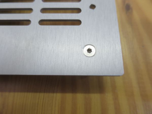
I don´t like plastic feets and i used diy aluminum feets.
The countersink screw is under the bracket later 🙂


Again, in my opinion a DIYer should have enough cable in the drawer.
For the PSU connection I didn´t use the cable of the kit 😉

Kind regards
Andreas
I don´t like plastic feets and i used diy aluminum feets.
The countersink screw is under the bracket later 🙂


Again, in my opinion a DIYer should have enough cable in the drawer.
For the PSU connection I didn´t use the cable of the kit 😉

Kind regards
Andreas
Many thanks for the replies guys 🙂
I just did a blank mounting and indeed there isn't enough cable. Not a problem, I have enough on my side, but it also enabled me to see other bits such as how to mount the entire unit properly and also while being able to dismantle it should I want to try other FE or other filters.
I am looking into stand-offs and connectors as access is limited and one needs to be inventive if wanting to perform quick A-B comparisons. While at it, I found that raising the filter, using stand-offs, helped relocating it (up and behind) resulting in having probably enough cable then.
Looking into FE mounts and connections right now...
Thanks again for all those who replied: you saved me a lot of hassle: I needed indeed some thinking before cutting cables or even doing the final assembling - not that it is a majour problem but not a 2h job at the office for my limited skills obviously.
Enjoy music
Claude
Building a special amp such as this is about the journey as well as the destination. My initial effort on the external linear PSU was in part proof of concept. Next thing is to make it look finished. Gathering some more parts as well..
Couldn't agree more! Having largely shelved my DIY audio hobby for a good ~10 years or so, I've been relishing the process of working through some projects once again. Perhaps it was the extended break, but I've found a whole new level of enthusiasm for the planning, construction, and excitement of finally flipping the power switch to hear (and hopefully not smell) what comes out - an unexpected delight!
Personally, I have also noted a significant shift in my own mindset vis-a-vis my approach to the hobby. I'm much more interested now in producing a very polished completed project - no longer is the focus just on experimenting and getting something working well, but also setting the aesthetics much higher on the priority list. It's more time consuming, of course, as I've always found the mechanical aspects of a project to be the most challenging. I've learned that the long-term experience of "living with your own creation" needed greater consideration up front. No regrets, however, about any of the less-appealing projects I've built in the past - they are good motivation to build anew, but better! 😎
...I suppose that's a long way of saying that this project is a real treat!
A worthwhile experiment to hear how quiet an amp can be performed by connecting headphones to the output of an amplifier. ... Try it as a headphone amp and you will hear what this amp is capable of in terms of resolving detail. It's a nice way to enjoy your VFET late at night without disturbing others in the house.
... a truly fine idea! I'll have to give this a go when mine is finally ready to go.

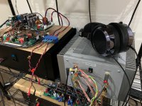
It's easy to do once you have a handy TRS headphone jack to speaker cable adapter.

Here is the headphone connected to my VFET (No. 010). I am using a SE/balanced hybrid SS/tube buffer stage with 14dB gain to drive everything.

Here is the headphone connected to my VFET (No. 010). I am using a SE/balanced hybrid SS/tube buffer stage with 14dB gain to drive everything.
Attachments

Last edited:
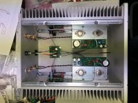
I’m so close.
It’s been a long week and was hoping to hear music tonight...just burnt out after finishing the wiring.
So hopefully tomorrow I’ll sort out the last few things like mounting the PS Filter board and bottom cover.
Then I can cross my fingers and power it up.
It’s been a long week and was hoping to hear music tonight...just burnt out after finishing the wiring.
So hopefully tomorrow I’ll sort out the last few things like mounting the PS Filter board and bottom cover.
Then I can cross my fingers and power it up.
Attachments
No worries. The amp will sound just as wonderful when you get it finished.
It initially takes a half hour to warm up. Then you can adjust the bias voltage (Vds across the VFET), wait another half hour to confirm, then button down the top cover.
As we have noticed the amp does exhibit a run-in period. It will need a days worth of being on before it starts to sound really good. And it will continue to improve over the next 100 hours.
Last edited:
Some news from N. 22 🙂
It has all been treated to death, so nothing really new and perhaps some common sense, but well, I thought why not sharing and summarizing it here.
The kit is great but I strongly recommend you do some test fitting before going for the real assembling. You may discover a lot of things that are more apparent when you have the real Mc Coy in 3D in front of you rather than just pix or bare measurements.
A few bits I did...
0) Check the C1 caps on the OS boards have the right orientation and R7 is on the filter board. I am lucky, no early boards...
1) The LS terminals are great quality, no doubt on that. The crimping bits less so in my case, but no drama of course. Not a problem to crimp if you have the right equipment (crimping tool with a "rack"), but a nightmare re tolerances. I spent over 1h to adjust every single bit with blades and screwdrivers and pliers to make sure they fit correctly. They were all way too tight, very difficult to fit and would have been impossible to undo in situ (well taking into account the small recess). I would advise you try all the parts before assembling and make sure they fit tight while being able with moderate forces (and no pliers) to undo them.
2) The kit is easy to solder, really well done, very straight forward to assemble all boards. There is one bit that can be a bit of a hassle though: the SMPS power connector wires. I am used to SMD & Co, but this is a different problem. OK, not a majour one, but sadly not the 5 min job I expected to get the 4 wires on the connector. It is not easy to get the cables in the right position (and no, adding some solder before hand on the small connector legs as done usualy didn't help at all in my case, on the contrary). And of course, the more you progress, the more space gets cramped, so plan beforehand. I am lucky to have a thin soldering iron with a 0.3mm tip and a remote power station...
3) You may want to use tall metal stand offs. For the input filter anyway, as that helps a lot future doing and undoing (you just let them at the floor, easy location) plus it gives way more margin re cable length. Further, it allows also to move the filter back or further way (see poor pix), and that helps cabling and also possibly future upgrades re additional filters with an additional board, who knows, if Mark releases it...
4) I am also considering metal stand offs for the FE boards, as that would in conjunction with possibly legs or connectors enable quick swaps. And if long enough, still enough space for it while moving away from the heatsinks, which opens the door with quick connectors and stand offs to fit parts underneath the board in case of caps bypassing with PPP. Oh, and turning them 180° is under consideration aswell, making things easier if wanting to play. Ok, won't be isostatic as only 2 screws / stand offs then, but it is OK.
Still thinking... I really like soldered connections, and don't like connectors with screws or crimping, but then I must confess it works fine as I found out so... time to change my mind and be practical...
5) The chassis is really gorgeous, the markings top. Assembling it can be time consuming if you do it for the first time. If so, you really want to adjust the rails to the rear pannel (so the big front pannel has the rail gap), as advised earlier here. I use a straight wooden block to make sure everything was straight and flush and with no play, basicaly not tightening the screws, pushing with hands and wooden block and tightening then the rails. Of course all the rest needs now to be undone to enable the real assembling, but as you did it once you know exactly what to do and you learned that without having the valuable boards on it. Dry fitting is key... things that look symmetrical might not be it, finish of the pannels is side sensitive etc.
The attached pix are miserable, but really just to give some ideas and add some colours, little added value 🙂
Enjoy music
Claude
Attachments
- Home
- Amplifiers
- Pass Labs
- DIY Sony VFET Builders thread