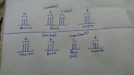
Yes, correct as I see it.
You should have a low resistance from Yellow to Blue.
Low resistance from Red to White.
Open circuit from Blue to Red.
You should have a low resistance from Yellow to Blue.
Low resistance from Red to White.
Open circuit from Blue to Red.
View attachment 957562
So you can move the 8V winding to the left, and relabel the wires as shown on the schematic, while inverting the polarity. And that will give you 28V and 36V with the opposite AC polarity of the other 28/36 winding.
Then you can use the circuit with the 2 bridge rectifiers and it will work.
Can you please tell me how to move the 8V winding to left.
How to invert polarity(assuming it needs to be done only on one set of secondary).
If that saves me 2 rectifiers.
Does this make sense?
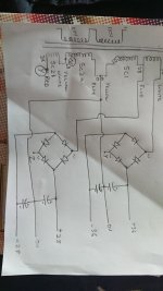
I've added the phase dots to help.
Leave secondary one (Sc1) as is.
Join the altered secondaries (Sc2a and Sc2b) Yellow to White.
Join the original Sc1 Yellow to Sc2a Blue.
Now Sc2b Red is the 36 volt AC out, Sc2a/b Yellow / White is the 28 volt AC tap and Sc2a Blue is the 0 volt connection.
Test by measuring the AC volts from Sc1 White to Sc2b Red, it should be 72 volts. And from Sc1 Blue to Sc2b White should be 56 volts AC.
Attachments

Last edited:
> Can you please tell me how to move the 8V winding to left.
It's just a graphical representation on the drawing.
Basically you have one 28V and one 8V winding in series. They are connected like this (top):

So if you decide "0V" is on the left you get 28V and 36V but with the wrong polarity relative to the other winding in the transformer, which is your problem.
If you decide "0V" is on the right you get the correct polarity but you get 8V and 36V, so the 28V is missing.
So the 8V and 28V windings can be in series, but you simply have to swap them, like in the drawing Alan just posted.
Then you can rewire them in series, so the transformer will have 3 wires for these 2 windings, or you can keep 4 wires, as you wish.
It's just a graphical representation on the drawing.
Basically you have one 28V and one 8V winding in series. They are connected like this (top):
So if you decide "0V" is on the left you get 28V and 36V but with the wrong polarity relative to the other winding in the transformer, which is your problem.
If you decide "0V" is on the right you get the correct polarity but you get 8V and 36V, so the 28V is missing.
So the 8V and 28V windings can be in series, but you simply have to swap them, like in the drawing Alan just posted.
Then you can rewire them in series, so the transformer will have 3 wires for these 2 windings, or you can keep 4 wires, as you wish.
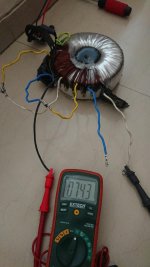
First of all a big Thank you to all of you for getting on to paper, drawing everything to help me understand the steps. With your help I was able to make all changes and get desired results.
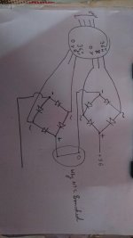
I think now I understand what you meant by symmetrical secondary. Now i am getting 72V and 56V. Attaching diagram with rectifier, looks good?
Since Yellow represents 0V in Sc1
If I swap Blue-Yellow Sc2a it shouldn't matter as its not a short?
Connecting sc2a blue to sc2b white but not to red.
I have a question, before transformer modification I was doing some test. When you connect +ve of one rectifier with -ve of another as in diagram, why did NCT started glowing. The circuit on secondary is still open soo how can large current be drawn? Am I misinterpreting anything?
I am looking for Heatshrink tape for insulation.
Can I use commonly available Epoxy to fill the center?
Attachments
Last edited:
Sorry for not being elaborate.
I am talking about Thermistor CL-60 connected on Primary side like in any PSU here on this forum 240V configuration.
I am talking about Thermistor CL-60 connected on Primary side like in any PSU here on this forum 240V configuration.
Now I am getting 72V and 56V. Attaching diagram with rectifier, looks good?
Since Yellow represents 0V in Sc1
If I swap Blue-Yellow Sc2a it shouldn't matter as its not a short?
Connecting sc2a blue to sc2b white but not to red.
Yes the diagram looks good.
No you cannot swap the Sc2a and Sc2b wires around.
It does not cause a short that is not the problem. It is to do with the 'phase' of each winding. I drew phase dots on the diagram in post #45. As long as those dots are all one above the other the windings are 'in phase' and you get the full voltage out. If you turn the secondary windings round (so the dots point away from each other) they are 'out of phase' and the voltage is zero.
That is the problem you started with and why you have reversed the connections of Sc2a and Sc2b? Hope that helps.
I have a question, before transformer modification I was doing some test. When you connect +ve of one rectifier with -ve of another as in diagram, why did NCT started glowing. The circuit on secondary is still open soo how can large current be drawn? Am I misinterpreting anything?
The only high current paths in that 2nd diagram are the windings and rectifiers.
Make sure the rectifiers are not shorted.
Make sure you have not accidentally connected AC to the +ve and -ve terminals?
I thought it was just the symmetry. Understood.Yes the diagram looks good.
No you cannot swap the Sc2a and Sc2b wires around.
It does not cause a short that is not the problem. It is to do with the 'phase' of each winding. I drew phase dots on the diagram in post #45. As long as those dots are all one above the other the windings are 'in phase' and you get the full voltage out. If you turn the secondary windings round (so the dots point away from each other) they are 'out of phase' and the voltage is zero.
That is the problem you started with and why you have reversed the connections of Sc2a and Sc2b? Hope that helps.
Earlier they were not, but after connecting they were 😀The only high current paths in that 2nd diagram are the windings and rectifiers.
Make sure the rectifiers are not shorted.
When I connected +of one to -ve of another there was a spark sound and some silver stuff came out of rectifier and thermistor started glowing.
No, AC to AC terminals. Only connected one positive into negative of the other. This happened before changes, so not doing it again until I have couple more rectifiers and NTC.Make sure you have not accidentally connected AC to the +ve and -ve terminals?
I am not going to pot them again, it will be just be a bolt and rubber base and top.
For transformer Insulation I am using Kapton tape.
Is that all right?
If you are talking about Primary winding, there is no continuity between pairs. Can be connected in Series(240V) or parallel(120V).Is there continuity between both windings?
- Home
- Amplifiers
- Pass Labs
- Powering two PSU from one Transformer