I have finally assembled two of these amps and have taken some voltage measurements on one, with no load and no input. The output inductor was not connected.
The output offset voltage was 0.1mV which I have repeatedly tested and find hard to believe! The transistors are all matched for hfe and the critical caps are all silver mica and resistors are all 1% metal film. The MOSFETS are Exicon single die devices and according to the spec sheets have the same input capacitance so i have not tried to better match them. The 220pF cap across the zener-diode network on the N-channel device was also not used.
I am interested in your comments and recommendations, especially around the bias setting. The driver BJTs get quite warm as expected at these high currents and i will refit the heatsink that I temporarily removed.
Otherwise it sounds Ok when connected to my "ESP P88", DC spkr protection and output inductor and B&W test spkr.
View attachment Simple MOSFET amp.pdf
>The output offset voltage was 0.1mV which I have repeatedly tested and find hard to believe!
Yeah, all these amps I built within last year (with op-amp in the input) have very low output offset. Amazing.
>The driver BJTs get quite warm
Some people say TO-126 can do up to 1W without heatsinking, but I always use solid heatsink to keep them under 50 degrees C.
>especially around the bias setting
My conclusion from the sim , was to keep idle current at 40mA.
With dual-die latfets I went for 80mA.
>it sounds Ok
Just OK?
..."Just Ok". I need to put on a better music source. Led Zep doesnt bring out the best in amps or speakers.
With these single die devices, I will be aiming for a total current draw close to 70mA which should mean the MOSFETs draw ~40-42mA.
I dont expect that the driver current will change much and so the heat dissipated will be around 0.69 W each. I have made the driver h/s from a single piece of angle aluminium and so i can add additional diffusers like those used on memory chips, to the top if really needed.
I am using Fairchild drivers and they can do 7W @ 25C or 1.2W @125C so the h/s i have made should be Ok.
Is there anything to be gained by increasing the supply voltage to the LT1056 from nominal 13V to say 15V?
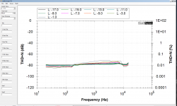
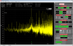
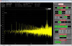
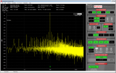
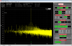
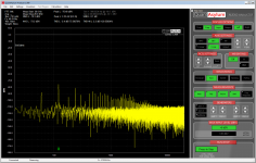
I tried to measure my amp (dual-die fets) with QA401 - again.
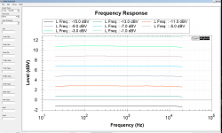
This time I have slightly different setup, including new resistor load with different signal pickup for QA401 analyzer.
Screenshots attached.
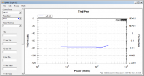
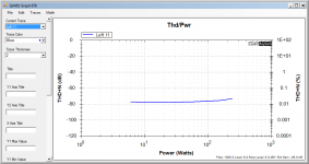
Thd at higher power level is increasing - it starts clipping too soon.
This was tested with PSU +/- 42V DC (instead of 50V).
This time I have slightly different setup, including new resistor load with different signal pickup for QA401 analyzer.
Screenshots attached.
Thd at higher power level is increasing - it starts clipping too soon.
This was tested with PSU +/- 42V DC (instead of 50V).
Attachments
-
 Thd_vs_Freq_power.png64.3 KB · Views: 92
 -
 power_thd_10kHz.png27.8 KB · Views: 92
 -
 power_thd_1kHz.png27.8 KB · Views: 99
 -
 freq_response.png62.8 KB · Views: 98
 -
 70W.png145.6 KB · Views: 328
 -
 40W_10kHz.png144.3 KB · Views: 335
 -
 30W.png143.9 KB · Views: 336
 -
 6W_10kHz.png145.6 KB · Views: 334
 -
 1w.png143.1 KB · Views: 346
42V for double die devices (or two pairs of singles) seems too low and I am not too surprised to see clipping when pushed hard. I would have expected that for 100 - 120W RMS, you would need 56V rails with laterals to be perfectly comfortable and of course, your PSU has to have the grunt to not dip too much (lots of uF and VA).
For my single dies i am aiming for around 50W and using 42.6v rails with a 500VA toroidal transformer that I happen to have available...Not likely to get any PSU droop, esp with 48000uF.
For my single dies i am aiming for around 50W and using 42.6v rails with a 500VA toroidal transformer that I happen to have available...Not likely to get any PSU droop, esp with 48000uF.
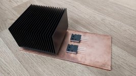
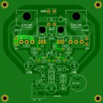
Work in progress. Finally I ordered Exicon ECW20N20/P20 Lateral MOSFETS from Profusion. Minek’s works are really inspiring, so I decided I’ll build the amp on a copper plate with a passive PC cooler. The PCB looks a little funny, reminiscent of a crystal skull  , but I hope it will work well.
, but I hope it will work well.Attachments
Last edited:
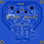
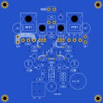
In the meantime I measured EXICON Fets, they are much bigger than as shown on the original PCB drawing, so I modified my layout. Someone suggested placing 100nF capacitors as close to the opamp supply rails as possible, and using separate ground tracks to the star point. This allows us trying much faster opamps without risk of oscillatiion.
Attachments
Last edited:
In the meantime I measured EXICON Fets, they are much bigger than as shown on the original PCB drawing
The ECW double-die devices are TO264, not TO247, so are 20mm wide, not 16mm wide.
and you can make the gerber
and version with 4x mosfet
You mean 4x LATFET?
PS: Profusion confirmed ECW20N20/P20 have built in gate protection diodes
Last edited:
>Since I am not a native English speaker, would you please explain what is meant by "double-die"?
>I know what "double" and "die" are, but so together .... Thank you.
it's like two transistors in one case. Matched, and with internal source resistors built in.
Equivalent of two separate fets. That's why they are bigger, and have much higher power ratings.
>I know what "double" and "die" are, but so together ....
Thank you. it's like two transistors in one case. Matched, and with internal source resistors built in.
Equivalent of two separate fets. That's why they are bigger, and have much higher power ratings.
>I decided I’ll build the amp on a copper plate with a passive PC cooler
Please note, that S (source/emitter) pins of the fets are connected to the metal pad (different than hexfets (they use collectors)).
Both Fets DO NOT need insulators between them and Hetasink, as long as you keep both channels isolated.
In my build all fets (4 of them) were mounted to the common chassis, so I had to use insulators,
but in the Wiederhold amp, with single-die latfets, I used 2 copper plates, with passive heatsinks, and no insulators used.
Copper plates were mounted on common WOODEN slab.
Last edited:
- Home
- Amplifiers
- Solid State
- LatFet Amp Based on Philips AH578