Basically I connect a Y2 safety capacitor between signal/power ground and chassis ground, then I connect chassis ground to PE.
I am used to "Audio GND" which also is "GND"/"Masse" in equipment (i.e. the 0 point of the secondary side of the PSU) and a metal casing connected to PE (i.e. the mains voltage side of affairs). Then a 100 Ohm with a cap in parallel can be used to connect Audio GND to PE for various purposes leakage being one of them. I am not familiar with "Chassis GND" as chassis or casing normally is not part of the circuit but simply connected only to PE for safety.
So then "chassis GND" and "PE" would be one and the same...
* I am also pretty sure GND pin 4 (now called "Com" for a change) of the RAC20-15DK should be connected to GND.
So then "chassis GND" and "PE" would be one and the same...
* I am also pretty sure GND pin 4 (now called "Com" for a change) of the RAC20-15DK should be connected to GND.
Last edited:
Signal/power ground is what you refer to as audio ground I believe, and chassis ground is basically just the metal casing you refer to 🙂 I think we're on a similar page here
Chassis GND is how almost every tube circuit was wired in the old days.
I still use it on point to point wired chassis. Chassis is ground. Signal, Power, Earth, all common. Even the heaters can be run with one wire and the chassis as return. Not a new concept, but almost pointless with circuit boards. They all still get tied together in my builds, but it's more of a star grounding than bus.
I still use it on point to point wired chassis. Chassis is ground. Signal, Power, Earth, all common. Even the heaters can be run with one wire and the chassis as return. Not a new concept, but almost pointless with circuit boards. They all still get tied together in my builds, but it's more of a star grounding than bus.
Yeah and it was wrong and it is still being copied by people that don't know correct grounding. Even more wrong and more common is not to use PE at all (while using 3 pin IEC sockets WITH PE pin...) and use the chassis for Audio GND. Such practices are only common amongst tube people and I have a hobby to solve hum and safety matters for them so I know the drill. It is plain ignorance/lack of knowledge of regulations and standards. It worked in old radios but when connecting various devices the issues will come up.
Please look up class I and class II and do things right for a change.
Please look up class I and class II and do things right for a change.
Last edited:
Good point. The RAC10-K units switch at 100kHz, so I assumed I just needed to do a standard low-pass. I have a Rigol DS1054Z I can use to analyse the noise (once I actually buy the units).
OK, your scope can do that. Note noise depends on load current so you must measure it with a load that draws about the same current as the amp. A resistor is fine.
You can measure output noise in differential mode, and also common mode noise between Earth (case) and output ground.
It wasn't wrong. It was just how things were done before they modernized the standards. At least in North America anyway.
You are implying somehow that connecting all grounds to Earth is dangerous. This is clearly false. If I want to "chase hum" I don't lift ground, I correct the problem or use audio isolation transformers.
When I was a kid, I had a ground loop caused by using CATV for the FM antenna once, but only if the computer was connected to the amp and it was grounded. For years, I lifted the ground on that computer to solve the issue (different branch circuits). Now, I use digital output from the computer - I'm not 12 years old anymore. I also ground my self designs where most commercial audio amps are not grounded (class 2?)
The only metal chassis I don't connect to Earth are those that run from 12V bricks.
Last edited:
Now it is wrong and we live now so anything that is being built now should be built according current knowledge. As last time we crossed paths you again chose to read things I don't write. Reading is an art. Certainly I am NOT implying somehow that connecting all grounds to Protective Earth is dangerous, you make that up. It will be safe that way but other issues will follow of course being solved by transformers 🙂 I know many tube people don't know correct grounding and I see illegal and unsafe practices mainly amongst these guys. This is because the threshold is low so it attracts many amateurs which in itself is fine but somewhat contradictory as the voltages are often lethal. Therefor many tube guys are not exactly experts in doing things according safety regulations and electrical standards (let alone standardized signal levels and impedances...) so I politely ignore any advice on this subject from them 😀 I can only be glad that they usually don't design, build or modify source devices.
Last edited:
You politely ignore them by insulting them. At least that's what I take away from your comments.
It's true, there are many people who don't understand the concept of ground at all. There's even a long sticky thread about it.
You said
You said
Perhaps English isn't your first language and your thoughts are being lost in translation. I could be misinterpreting you.
It's true, there are many people who don't understand the concept of ground at all. There's even a long sticky thread about it.
You said
but it wasn't wrong. It might be wrong now but it wasn't then.Yeah and it was wrong and it is still being copied by people that don't know correct grounding
You said
which implies I do everything incorrectly (tying all grounds together isn't a safety violation) yet you say you didn't imply that?Please look up class I and class II and do things right for a change.
Perhaps English isn't your first language and your thoughts are being lost in translation. I could be misinterpreting you.
Last edited:
Please practice the art of reading and interpretation and stop playing word games. I don't need to explain I am not a native English speaker and this IS an international forum but feel free to continue in German, Dutch, French or Turkish.
Wrong practice and you know it.
Chassis is ground. Signal, Power, Earth, all common. Even the heaters can be run with one wire and the chassis as return.
Wrong practice and you know it.
Last edited:
BucketInABucket, I just read the data sheet of RAC20-15DK again and output ripple and noise is 1% of Vout so 150 mV p-p! Yes that is milliVolts.... 53 mV rms so the filtering is an absolute must.
I think it a good idea to have the RAC20-15DK followed by an LC filter and then LDO regs like LT3045 and LT3094. Only 0.235 V dropout at 500 mA. You won't loose much when you set them for example at a safe +/- 14V (check if the HPA accepts this). Rejection will be higher than just LC filtering. Dissipation will be acceptable but you may use separate regulators per channel if you want.
As remarked earlier, pin 4 should IMO be connected to Audio GND.
Last edited:
Please practice the art of reading and interpretation and stop playing word games. I don't need to explain I am not a native English speaker and this IS an international forum but feel free to continue in German, Dutch, French or Turkish.
Wrong practice and you know it.
Not "Wrong", there is nothing inherently wrong (from a safety standpoint) with it except you might have more noise. I wouldn't recommend this method with an AC powered phono stage.
The word you are looking for is "Best", not "Wrong".
J'men câlice pour votre attitude. Je pense tous est condescendant. Mais vive le forum libre! LOL
Tout le meilleur cependant.
For those in French speaking countries that don't understand Québec "Sacres"... Cours de Juron Quebecois (Pure Laine) - YouTube
Last edited by a moderator:
BucketInABucket, I just read the data sheet of RAC20-15DK again and output ripple and noise is 1% of Vout so 150 mV p-p! Yes that is milliVolts.... 53 mV rms so the filtering is an absolute must.
I think it a good idea to have the RAC20-15DK followed by an LC filter and then LDO regs like LT3045 and LT3094. Only 0.235 V dropout at 500 mA. You won't loose much when you set them for example at a safe +/- 14V (check if the HPA accepts this). Rejection will be higher than just LC filtering. Dissipation will be acceptable but you may use separate regulators per channel if you want.
As remarked earlier, pin 4 should IMO be connected to Audio GND.
Yeah dw pin 4 is connected, accidentally left it off as I hastily made the circuit diagram, hence the mistakes 😀
And yes I'm aware, that's why I was thinking about a CLCLC filter. I was also thinking about using 24V versions of those regulators and then regulating down to 18V but that is quite the voltage drop. I think something like a pi filter into LDOs would be an acceptable compromise.
I'm thinking of using TPS7A4701/3301 modules.
Last edited:
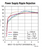
Watch out, PSRR of LDOs strongly depends on dropout.
Yes, they will be dropping 6V so should be alright 🙂
Did you see this discussion here?:
PO89ZB , an inline DC filter for SMPS wall warts . Preamps, HPA, Korg NuTube, etc
In post #540 is a bipolar filter that would fit your case.
That said, you can try your own filter of course; just mentioning it.
I don´t know the Recom converters but am using Traco and they behave very well with a bit of capacitance and are low noise enough, even for more sensitive circuitry.
If the Recom shows ill effects due to that little capacitance you could always change L1 for a resistor or add one in line with L1.
My last headphone amp uses a Meanwell 12V/2A (for now) without extra filter for eventual high-frequency noise. It literally is so quiet I often want to switch the amp on when it already is. It is regulated, doesn´t sag and has very little ripple in the audio band.
So don´t be afraid of that switcher but include some kind of LC-filter and keep it close to the converter.
PO89ZB , an inline DC filter for SMPS wall warts . Preamps, HPA, Korg NuTube, etc
In post #540 is a bipolar filter that would fit your case.
That said, you can try your own filter of course; just mentioning it.
It´s not that much capacitance.Mainly worried about instability of the AC/DC module as some of them can't handle much capacitance on the output.
I don´t know the Recom converters but am using Traco and they behave very well with a bit of capacitance and are low noise enough, even for more sensitive circuitry.
If the Recom shows ill effects due to that little capacitance you could always change L1 for a resistor or add one in line with L1.
My last headphone amp uses a Meanwell 12V/2A (for now) without extra filter for eventual high-frequency noise. It literally is so quiet I often want to switch the amp on when it already is. It is regulated, doesn´t sag and has very little ripple in the audio band.
So don´t be afraid of that switcher but include some kind of LC-filter and keep it close to the converter.
You´re welcome. I like to skip the kiss for now😉
Also, it doesn´t hurt to ask if anybody has leftover PCBs. I´m sure many had them produced for themselves.
I also got "leftovers" from a fellow forum member.
Just to be sure I meant if fits your case as in your purpose not the actual case/enclosure so if you decide to use that PCB be sure it fits.In post #540 is a bipolar filter that would fit your case.
Also, it doesn´t hurt to ask if anybody has leftover PCBs. I´m sure many had them produced for themselves.
I also got "leftovers" from a fellow forum member.
Yes, they will be dropping 6V so should be alright 🙂
The heat will be a real issue to deal with. I don't know why but the LT regs are sensitive to heat. TPS regs are OK too. The LC should be capable to get that 53 mV down and the regs will make it work like a good linear PSU would have done: quiet.
It is surprising to see many favor SMPS but then accept the high noise and ripple and use an extra filter. It seems a bit like cutting a finger deliberately and then search for a bandaid. In your case the casing forces the choice but why are SMPS so in favor? Serious question as I see mostly trouble like HF/RF radiation (which the output filter won't solve) etc. with the vast majority of those. Again in this case one needs linear regs to get the situation as it should be for good audio... Is it the fear for mains voltage that shifted the preferences? Or is best possible quality not a goal, just "good enough"? Or is self built stuff not measured ?
Some others observing such an issue:
https://www.diyaudio.com/forums/eve...mps-killed-radio-reception-2.html#post6676807
Last edited:
- Home
- Amplifiers
- Power Supplies
- Filtering after encapsulated AC/DC module