Thanks for the explanation, WT. So for my application in a LuFo, I could set it up to get 3A using a 0.47ohm load and about 4.2v?
But what am I trying to match exactly? Or is matching even needed if each active is in a different amp and the bias current can be adjusted with a trimpot controlling the cascode above it?
All valid points. The only scenario where I would think it matters is if you were making SUSY version where both halves shared the same choke. You are matching Vgs at the operating point the same way NP matches parts that are paralleled in his beefy parallel OS arrangements.
@X and woofer
Thanks so much for your responses.
This is all excellent information that hopefully helps others continue to explore use of the LU1014.
I know I will be spending so more time reading the ZV9 manual and considering more of the designs that are popping up.
Thanks so much for your responses.
This is all excellent information that hopefully helps others continue to explore use of the LU1014.
I know I will be spending so more time reading the ZV9 manual and considering more of the designs that are popping up.
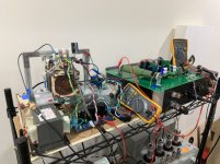
I ran the max power stress test on the little LD1014D’s mounted to my LuFo amp that I got from AliExpress (same link that Danny66 recommended). I ran full power at 39.5w for over 30min this is 3A bias current. I even took it to 6A bias current for a few minutes. Works fine and no magic smoke. I am pretty sure these are genuine. The LD’s are much easier to install on the aluminum IMS adapter PCBs.

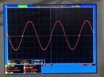
50.4vpp into 8ohms no clip:

50.4vpp into 8ohms no clip:
Attachments

X,
Great work. While the rest of us sleep, you're a machine! I'm convinced you don't sleep! You already have a full BOM for the LuFo on the other thread!
Since it is a SE output stage, I surmise it will be 20 watts into 4 ohms or 25Vpp. Can you test for that too?
Best,
Anand.
Great work. While the rest of us sleep, you're a machine! I'm convinced you don't sleep! You already have a full BOM for the LuFo on the other thread!
Since it is a SE output stage, I surmise it will be 20 watts into 4 ohms or 25Vpp. Can you test for that too?
Best,
Anand.
Hi Anand,
If you are interested in 4ohm operation, it would require a simulation to get the setpoints dialed in, but I think boosting the bias current to say, 4.5A and decreasing the supply voltage to 24v might yield quite a bit more power - circa 53w. This would be 30w dissipation across each of the MOSFETs, and about 15w across the LU1014.
If you are interested in 4ohm operation, it would require a simulation to get the setpoints dialed in, but I think boosting the bias current to say, 4.5A and decreasing the supply voltage to 24v might yield quite a bit more power - circa 53w. This would be 30w dissipation across each of the MOSFETs, and about 15w across the LU1014.
At Woofertester’s comment that the amp might sound better at 6A in general, I am going to double up the secondaries of my Antek 400VA 25v power trafo in parallel (currently unused waiting for 2nd channel). Crank bias up to 6A and stay at 28v and see if it sounds better (or measures better). I can handle the 150w dissipation from the 3 MOSFETs with this CPU cooler. It’s run there before no problem. This will be fun - although the amp is going to be a true room heater. Also with dedicated 400VA trafo and MOT each channel is heavy. Mandatory dual monoblock chassis now will be required.
Enjoy. This device is from my eBay stash.
20 Amps! Really?
20 Amps! Really?
Per the datasheet, the device is rated to 50A continuous, 100A pulsed and 69 watts at 25 deg C. From these numbers, it appears to me that the device was designed to be used in a switching power supply cascoded and run well into saturation. The datasheet states that +5V can drive the gate and take the device into saturation. This would include positive gate current which I will measure just for grins when all the mechanical parts arrive.
The fact that the device has a gorgeous triode behavior in the linear region is likely serendipitous. I doubt that the designers intended this.

I have tested the LuFo at 6A and 28.1v. It sounds wonderful and the bass is quite a doozy on my TLs.
LuFo amp running at 6.0A bias current and 28.1v. Driving 10F/RS225 TL speakers. - YouTube
LuFo amp running at 6.0A bias current and 28.1v. Driving 10F/RS225 TL speakers. - YouTube
Zen Mod's Kit package for his LuDEF amplifier are available in the Swap Meet.
Link- LuDEF Kit Packages
A perfect way to use your matched pair of LU1014D from Papa's stash!
Link- LuDEF Kit Packages
A perfect way to use your matched pair of LU1014D from Papa's stash!
Matched Pairs
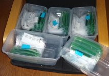
This is what hundreds of matched parts look like. My criteria for a matched pair is better than 2% different in Vgs at 2.4v Vds at 1.5A idle current (bias current of F3 amplifier).
The repeatability of this measurement with my setup is ~ 0.4%. Many of the matched pairs' difference are at or less than the repeatability of the setup. That means many pairs that are as close as can me measured with the equipment at hand.
The large population donated by Mr. Pass is what allows so many matched pairs and only 3 parts total that are not matched.
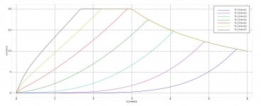
When you receive your matched pair, ignore the gain numbers. The gain (transconductance) is the slope of the line tangent to the Vgs-Id curve. It is different everywhere on the curve and denominator is a difference of two numbers so the calculation is very sensitive to noise. The repeatability of this measurement is not great compared to the repeatability of the Vgs measurement.
This is what hundreds of matched parts look like. My criteria for a matched pair is better than 2% different in Vgs at 2.4v Vds at 1.5A idle current (bias current of F3 amplifier).
The repeatability of this measurement with my setup is ~ 0.4%. Many of the matched pairs' difference are at or less than the repeatability of the setup. That means many pairs that are as close as can me measured with the equipment at hand.
The large population donated by Mr. Pass is what allows so many matched pairs and only 3 parts total that are not matched.
When you receive your matched pair, ignore the gain numbers. The gain (transconductance) is the slope of the line tangent to the Vgs-Id curve. It is different everywhere on the curve and denominator is a difference of two numbers so the calculation is very sensitive to noise. The repeatability of this measurement is not great compared to the repeatability of the Vgs measurement.
Attachments
Last edited:
X, the amp sounds GREAT! Impressive! Congratulation for designing and building such a nice amp so quickly. 
And thanks for doing all that testing.
And thanks for doing all that testing.
This is what hundreds of matched parts look like.
You deserve one of these;
An externally hosted image should be here but it was not working when we last tested it.
- Home
- Group Buys
- Lovoltech LU1014 Power Jfet Group Buy