Well, really excited to share that I purchased the parts kit, trying out a new currier service that hopefully results in shipment times of less than several months / lost packages!
So... I'm beginning to plan my journey, and I will have, as usual, many, many questions.
The first one is mechanical! I agree with most that this PCB is not only a great design, it is also very attractive in itself! So, showcasing it makes a lot of sense. Still, I have a kid and a cat, so going full-Monty is something that could result in catastrophe!
So... I have two possible designs that could showcase the PCB and it's components:

The left one uses a raised glass, while the other one uses a round looking window, blatantly copying Chord's approach (I will most likely be pairing this with a Chord Qutest).
So my question is mostly about heat: the first design would favor a lot of air flow, the second one will most likely be a very confined enclosure, and glass being a great isolator, would actually make things a bit worse.
That said, my Whammy in a similarly-sized enclosure lives perfectly fine and dissipates very little heat. Can I assume this is the same case here? Or do you guys think that the extra flow is a must? (obviously, I could make the second look be more vented, so that is another possible route).
I fully appreciate any feedback (and it can be an aesthetic feedback as well, these are the early stages of planning).
This render is conceptual, obviously it will have volume knobs, headphone plugins, input selector, switch? (that is a question for further down the road!). So, please us a bit your imagination if possible to envision the finished thing 🙂 .
Thanks for any feedback, really looking forward to this project!
Thanks,
Rafa.
So... I'm beginning to plan my journey, and I will have, as usual, many, many questions.
The first one is mechanical! I agree with most that this PCB is not only a great design, it is also very attractive in itself! So, showcasing it makes a lot of sense. Still, I have a kid and a cat, so going full-Monty is something that could result in catastrophe!
So... I have two possible designs that could showcase the PCB and it's components:
The left one uses a raised glass, while the other one uses a round looking window, blatantly copying Chord's approach (I will most likely be pairing this with a Chord Qutest).
So my question is mostly about heat: the first design would favor a lot of air flow, the second one will most likely be a very confined enclosure, and glass being a great isolator, would actually make things a bit worse.
That said, my Whammy in a similarly-sized enclosure lives perfectly fine and dissipates very little heat. Can I assume this is the same case here? Or do you guys think that the extra flow is a must? (obviously, I could make the second look be more vented, so that is another possible route).
I fully appreciate any feedback (and it can be an aesthetic feedback as well, these are the early stages of planning).
This render is conceptual, obviously it will have volume knobs, headphone plugins, input selector, switch? (that is a question for further down the road!). So, please us a bit your imagination if possible to envision the finished thing 🙂 .
Thanks for any feedback, really looking forward to this project!
Thanks,
Rafa.
I have one ACP+ in a Galaxy 2U case which doesn't get noticeably warm. The naked one is even cooler. I almost went with a design like your glass one using optical grade polycarbonate as the top but decided I liked naked too much. The one in the Galaxy goes to my son who has a toddler and a six year old and like you, cannot leave an open ACP+ around. FWIW, I like your glass top enclosure better.
Built Headphone Amp
Hi there.
Last week I "finished" my headphone amp.
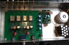
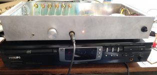
I built mine with the recommended components, except for the decoupling capacitor at the entry, which consists of two 4u7 capacitors in parallel. The heatsinks are hovering above the MOSFETs on a piece of alumininiun u-profile The case is made from scrap aluminium sheet welded together with Durafix.
The power source source is from an 2 * 12V Amplimo toroid transformer and a series of 1500uF smoothing capacitors. It's then followed by a super-regulator for which I built my own PCB.
I already sounds very nice. After my initial joy I read all the posts in this thread.
I then measured the voltages across R4 (125Ohm) the ""left part gives 760mV and the right 970mV. So I guess I have to lower these to make them run 10mA?
Another concern that I have is the static discharge on the volume knob I read about. I'm not sure how to mitigate this.
Speaking of grounding: do you people recommend putting the 0V level of the of the power supply to metal case. I already connected the GND of the power inlet to the case.
Hi there.
Last week I "finished" my headphone amp.
I built mine with the recommended components, except for the decoupling capacitor at the entry, which consists of two 4u7 capacitors in parallel. The heatsinks are hovering above the MOSFETs on a piece of alumininiun u-profile The case is made from scrap aluminium sheet welded together with Durafix.
The power source source is from an 2 * 12V Amplimo toroid transformer and a series of 1500uF smoothing capacitors. It's then followed by a super-regulator for which I built my own PCB.
I already sounds very nice. After my initial joy I read all the posts in this thread.
I then measured the voltages across R4 (125Ohm) the ""left part gives 760mV and the right 970mV. So I guess I have to lower these to make them run 10mA?
Another concern that I have is the static discharge on the volume knob I read about. I'm not sure how to mitigate this.
Speaking of grounding: do you people recommend putting the 0V level of the of the power supply to metal case. I already connected the GND of the power inlet to the case.
Attachments
Yes, you should lower the R4 to get 10mA.
As for grounding, are your stand-offs conducting the ground of the circuit board to the chassis? Check for continuity of PCB ground to chassis and make sure that there is continuity.
The volume control connection to the front panel should also have continuity, and the front panel should also have continuity to the chassis bottom plate and to ground. So this way, the PCB, volume control, and chassis are all grounded.
Yes, you should lower the R4 to get 10mA.
As for grounding, are your stand-offs conducting the ground of the circuit board to the chassis? Check for continuity of PCB ground to chassis and make sure that there is continuity.
The volume control connection to the front panel should also have continuity, and the front panel should also have continuity to the chassis bottom plate and to ground. So this way, the PCB, volume control, and chassis are all grounded.
All 6 sides of the case are electrically connected and the ground plane of the board is connected to the case via the bolts holing it in place. Besides that the volume knob is grounded also. Sorry for asking, I could have easily measured that before. I guess I got scared off zapping my fets.
For the 10mA, I read that other builders matched the J113, fets, but it seems to me that as long as they provide a 10mA current we are fine. Or are there benefits other than having two equal values for R4 in having matched Q3?
BTW: how precise does this 10mA have to be?
Last edited:
No sonic benefit as the J113 is a CCS, only regulating current to the J74.
I was asking about the continuity to ground as I see plastic washers /isolators on your stand-offs and between the volume control and front panel.
I was asking about the continuity to ground as I see plastic washers /isolators on your stand-offs and between the volume control and front panel.
No sonic benefit as the J113 is a CCS, only regulating current to the J74.
I was asking about the continuity to ground as I see plastic washers /isolators on your stand-offs and between the volume control and front panel.
Well spotted, I'll replace these with metal ones after I bought some. The bolts are not isolated though and make contact with the metal drill holes..
Well you could lower the glass in the round window with spacers to allow air to vent.
Well, really excited to share that I purchased the parts kit.........So... I have two possible designs.... the second one will most likely be a very confined enclosure, and glass being a great isolator, would actually make things a bit worse.....Thanks for any feedback
Right you are, William 2001, Q5 and Q6 indeed
I've reached the age where even writing things down doesn't help. I can't remember where I put the notes. Or a pencil.
I did remember to order a new stainless steel needle nose to bend the leads. The wrist strap, just a piece of 12 ga. copper soldered to a length of ground wire, I have.
"There's no virtue in being old, it just takes a long time" - (anon)
A wrist strap is not a bad idea if you have it. The more easily damaged part here is Q5 and Q6. ESD is certainly not a good thing for the health of those guys.
I've reached the age where even writing things down doesn't help. I can't remember where I put the notes. Or a pencil.
I did remember to order a new stainless steel needle nose to bend the leads. The wrist strap, just a piece of 12 ga. copper soldered to a length of ground wire, I have.
"There's no virtue in being old, it just takes a long time" - (anon)
Get a lab notebook and use it. The most popular notebook here where I live (Silicon Valley) is model number 43-648 by the National paper company.
link to Amazon purchase page
It's sturdy, full sized, has numbered pages, and each page is printed with engineering graph paper, 4 squares to the inch. Watch the video (!) on the Amazon page.
link to Amazon purchase page
It's sturdy, full sized, has numbered pages, and each page is printed with engineering graph paper, 4 squares to the inch. Watch the video (!) on the Amazon page.
Thanks! The not-too-much heat confirmation is what I expected. Nice to know for certain. Thanks also for the esthetic feedback! I’m actually leaning the other direction, but other than wasting a small area of aluminum, I think I can design for both looks, have both covers made and even make them interchangeable! Let’s see.I have one ACP+ in a Galaxy 2U case which doesn't get noticeably warm...FWIW, I like your glass top enclosure better.
Thanks ZM! In the past, the translation from CAD to actual product was reasonably similar, so I’m feeling confident, as long as my metal-sheet bender’s business survived the pandemic. I’ll keep everyone posted.Rafa, these are going to look awesome
Thanks. Yes, it could work. I would need to raise the height a bit, and I was hoping for a “leaner” look, but it’s certainly a path worth considering. Still, not sure I’m going to be able to order glass with holes for spacers, I need to talk to the glass cutter.Well you could lower the glass in the round window with spacers to allow air to vent.
Thanks again friends.
Rafa.
I neglected to say the obvious. Both look great--nice design. The smaller porthole has the effect if being alluring, makes one want to look inside. I'd be happy with either one.
That's a great start!! Does anyone know if the diystore kit has a UK power plug option? Store picture show a US plug and I can't see other options??
The wall wort SMPS included in the kit handles 250vac but needs the plug adaptor for the UK 3 prong type.
--Tom
Thanks Tom. For a multitude of reasons it's cool to see Pass designs using SMPS.
Nelson was really onto something. It really does lower the barrier to entry and can get the job done. With the proper SMPS output filtering in place, you may notice no difference between it and a linear supply in this application. And in the end, that is half the fun of diy audio - try both, then measure, learn, listen and enjoy. As Nelson has said before, this is entertainment not dialysis. 😉
If you want to learn more about the filtering, Mark Johnson designed a really well functioning (measurably and audibly) filter for SMPSs used for these applications and there is a kit in the store for this too. This is the thread to check it out:
PO89ZB , an inline DC filter for SMPS wall warts . Preamps, HPA, Korg NuTube, etc
Enjoy!
--Tom
I almost have my acp+ wrapped up. The default J113 and 127ohm R4 resistor gave the following:
Left - 0.813 (6.40ma)
Right - 0.806 (6.34ma)
Quick swap of R4 to 47.5ohm and I have ended with the following:
Left - 0.495 (10.42ma)
Right - 0.488 (10.27ma)
Is that right in the 10ma ballpark? or should I get both channels closer?
Thanks
Left - 0.813 (6.40ma)
Right - 0.806 (6.34ma)
Quick swap of R4 to 47.5ohm and I have ended with the following:
Left - 0.495 (10.42ma)
Right - 0.488 (10.27ma)
Is that right in the 10ma ballpark? or should I get both channels closer?
Thanks
This worries me a bit looking into my future build. There are no good local suppliers of resistors. Local availability is just kid's-projects type of resistors, very poor quality.... The default J113 and 127ohm R4 resistor gave the following ... Quick swap of R4 to 47.5ohm and I have ended with the following
Has anyone received the store's Parts Kit already? Are there any "spare" resistors to try to achieve this 10mA or is it so case-by-case that there is no way but to measure and buy the appropriate values?
That is going to be one expensive set of resistors for me if that is the case 🙁 .
Thanks for any feedback,
Rafa.

- Home
- Amplifiers
- Pass Labs
- Amp Camp Pre+Headphone Amp - ACP+