Hi, I was shutting down my preamp, after I finished building it and listening to it.
I was left with the doubt on the development of the follower cathode.
I have a CCS (C4S) set with 3.2mA by trimmer.
The valve is a 6n1p gold grid - gold pin.
....but i could also a tesla e88cc as an option to be mounted.
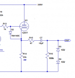
With the voltage values in the drawing I have the 6n1p grid at about -3.5v, I think, if I remember correctly.
I can do better?
I tried to center the tensions as much as possible, 138v is the practically exact goal of 275v.
I did a further research and I see that the 6n1p can also be crossed by 7 / 9mA. Are my 3.2mA few?
According to you the voltages are compatible with the assembly of an e88cc ... then I adjust the ccs to a correct current (?).
I don't want to touch the Ra of the previous stage, this maybe puts me some limits. Unfortunately I don't know how to use simulators.
Is it more important that the Vg of the CF is central to the B + or is the negative value of the grid more important?
PS: in the drawing I wrote ecc88 in brackets ... but the one I can put in it is an e88cc.
The stage preceding the follower cathode is ecc83.
I drive 3,5mt of signal cable and enter an amplifier with 20k input.
Thanks in advance for any advice.

I was left with the doubt on the development of the follower cathode.
I have a CCS (C4S) set with 3.2mA by trimmer.
The valve is a 6n1p gold grid - gold pin.
....but i could also a tesla e88cc as an option to be mounted.
With the voltage values in the drawing I have the 6n1p grid at about -3.5v, I think, if I remember correctly.
I can do better?
I tried to center the tensions as much as possible, 138v is the practically exact goal of 275v.
I did a further research and I see that the 6n1p can also be crossed by 7 / 9mA. Are my 3.2mA few?
According to you the voltages are compatible with the assembly of an e88cc ... then I adjust the ccs to a correct current (?).
I don't want to touch the Ra of the previous stage, this maybe puts me some limits. Unfortunately I don't know how to use simulators.
Is it more important that the Vg of the CF is central to the B + or is the negative value of the grid more important?
PS: in the drawing I wrote ecc88 in brackets ... but the one I can put in it is an e88cc.
The stage preceding the follower cathode is ecc83.
I drive 3,5mt of signal cable and enter an amplifier with 20k input.
Thanks in advance for any advice.
You are missing a protective diode between grid and cathode on the CF stage.Hi, I was shutting down my preamp, after I finished building it and listening to it.
I was left with the doubt on the development of the follower cathode.
I have a CCS (C4S) set with 3.2mA by trimmer.
The valve is a 6n1p gold grid - gold pin.
....but i could also a tesla e88cc as an option to be mounted.
With the voltage values in the drawing I have the 6n1p grid at about -3.5v, I think, if I remember correctly.
I can do better?
I tried to center the tensions as much as possible, 138v is the practically exact goal of 275v.
I did a further research and I see that the 6n1p can also be crossed by 7 / 9mA. Are my 3.2mA few?
According to you the voltages are compatible with the assembly of an e88cc ... then I adjust the ccs to a correct current (?).
I don't want to touch the Ra of the previous stage, this maybe puts me some limits. Unfortunately I don't know how to use simulators.
Is it more important that the Vg of the CF is central to the B + or is the negative value of the grid more important?
PS: in the drawing I wrote ecc88 in brackets ... but the one I can put in it is an e88cc.
The stage preceding the follower cathode is ecc83.
I drive 3,5mt of signal cable and enter an amplifier with 20k input.
Thanks in advance for any advice.
A 1n4148 will do just fine.
You should also have a resistor at the very output to prevent damage of the poweramp if the cable is connected after power off. Myself would use a much smaller output cap and avoid an electrolytic here.
Thanks, I used, between the grid and the cathode, a neon bulb instead of 1n4148 / 1n914.
They put a 100ohm R on the output.
The 10uF cap is a Russian Mbgo-2. I'll try its worth.
Do you have any advice on how much regular current with the C4S for the 6n1p or any e88cc that I would have?
Currently I set it to 3.2mA on 6n1p.
Thanks 🙂
They put a 100ohm R on the output.
The 10uF cap is a Russian Mbgo-2. I'll try its worth.
Do you have any advice on how much regular current with the C4S for the 6n1p or any e88cc that I would have?
Currently I set it to 3.2mA on 6n1p.
Thanks 🙂
6N1P is entirely different tube to ECC88. Check the data sheets
I knew it was different despite the Russians trying to pass it off as equivalent. Do you have to recommend an optimal current current (I set it with a trimmer with C4S) for 6n1p and e88cc that I would like to try?
Thanks again.
The "Russians" don't don't pass it off as an equivalent, unscrupulous or uninformed sellers do. They are similar in gain but have different transconductance. The 6n1p was developed as a miniature replacement for the 6n8s in new designs, and is fairly similar to the western 6BQ7.
The Russian 6n23p is a very close true 6DJ8/ECC88 equivalent, however.
My recommendation is to run it a at a bit higher current, as the output impedance will go down. Shoot for like 60-75% of it's maximum dissipation. It's a cathode follower so you don't have to worry about too many other details there, as it's cathode voltage will track the plate of the previous stage.
If the load is high enough increasing the current is useless , just cooking the tube , after all there are some 12AX7 ( ECC83 ) cathode followers in vintage or also newer amps 😀
Output impedance is not changing that much with current , only if you push the tube to the maximum current , the transconductance vs current curve will show you that .
Output impedance is not changing that much with current , only if you push the tube to the maximum current , the transconductance vs current curve will show you that .
Last edited:
I understand, yes but I have a 6n1p not a weak ecc83.
I also considered trying a tesla e88cc, always as a follower cathode.
I was wondering about the current because I have a difficult load to drive, 3.5mt of signal cable and 10k of an amplifier. thx
I also considered trying a tesla e88cc, always as a follower cathode.
I was wondering about the current because I have a difficult load to drive, 3.5mt of signal cable and 10k of an amplifier. thx
10k input impedance might be a small resistor across the input. Have you examined the poweramp if you can increase the input impedance ?
No, I actually haven't looked at it.
Unfortunately it is assembled and wired in such a way that taking it out and opening it would take a lot of work. It is a QSC GX5.
And have 20k imput, not 10k! I spelled it wrong!
Unfortunately it is assembled and wired in such a way that taking it out and opening it would take a lot of work. It is a QSC GX5.
And have 20k imput, not 10k! I spelled it wrong!
The "Russians" don't don't pass it off as an equivalent, unscrupulous or uninformed sellers do. They are similar in gain but have different transconductance. The 6n1p was developed as a miniature replacement for the 6n8s in new designs, and is fairly similar to the western 6BQ7.
The Russian 6n23p is a very close true 6DJ8/ECC88 equivalent, however.
My recommendation is to run it a at a bit higher current, as the output impedance will go down. Shoot for like 60-75% of it's maximum dissipation. It's a cathode follower so you don't have to worry about too many other details there, as it's cathode voltage will track the plate of the previous stage.
Help me remember, please. To know the power dissipated by the tube I have to do 190v (voltage between the anode pin and the cathode pin) x 0.0032A = 0.6w. The power dissipated by a tridode is this. Correct?
Then I will calculate the 60/75% of 2.2w which is the dissipable power of each triode of 6n1p.
Thanks again. I finished!
6N1P similar to 6N23p
Not at all. ECC88 is very similar to 6N23 BUT 6N1P is very different to both of them.
Cheers
Ian
Putting a NE2 neon across the grid and cathode will only 'fire' (ionize) at +/- 90Volts.
After 'firing' (ionizing), it will decrease to 60V.
That means if the grid goes 90V more positive than the cathode, the neon will fire.
But the grid can never get 90V more positive than the warmed-up cathode, because the grid wire will be 'smoked' first.
And if the grid is going 90V more negative than the cathode, the neon will fire.
But in your circuit, the grid can not get 90V more negative than the cathode.
If your CCS current sink can work at + 100 Volts, then if you put a neon between the grid and ground, the neon will fire if the input tube warms up slower than the cathode follower tube.
But putting a 90V transient from the cathode follower to the input of your 300W amplifier, might cause a failure of your 300W amplifier, or a very large transient to blow out your speaker.
You have some work ahead of you to make your cathode follower work properly, reliably, and to keep it from blowing out the 300W amplifier.
That 4uF cap at the cathode follower output blocks DC, but until it charges, it passes a very bad turn on transient to your 300W amplifier.
Your schematic is too simple for the application you are using it for.
Last edited:
At start-up for direct coupled stages the grid will see full B+ and the cathode is at ground potential ... so the neon could help ( if it is glowing in this situation obviously ) ... but usually tubes can live without this protection anyway . Probably it is far more dangerous to pull out the first tube while the amp is in operation .
Last edited:
Putting a NE2 neon across the grid and cathode will only 'fire' (ionize) at +/- 90Volts.
After 'firing' (ionizing), it will decrease to 60V.
That means if the grid goes 90V more positive than the cathode, the neon will fire.
But the grid can never get 90V more positive than the warmed-up cathode, because the grid wire will be 'smoked' first.
And if the grid is going 90V more negative than the cathode, the neon will fire.
But in your circuit, the grid can not get 90V more negative than the cathode.
If your CCS current sink can work at + 100 Volts, then if you put a neon between the grid and ground, the neon will fire if the input tube warms up slower than the cathode follower tube.
But putting a 90V transient from the cathode follower to the input of your 300W amplifier, might cause a failure of your 300W amplifier, or a very large transient to blow out your speaker.
You have some work ahead of you to make your cathode follower work properly, reliably, and to keep it from blowing out the 300W amplifier.
That 4uF cap at the cathode follower output blocks DC, but until it charges, it passes a very bad turn on transient to your 300W amplifier.
Your schematic is too simple for the application you are using it for.
Unfortunately I didn't understand much of your post.
A little because of my ignorance on the subject .. and a little because I don't know English well.
What I can say is that my output cap is 10uF (I don't think it changes compared to your speech) and that between the grid and the cathode I put two neon bulbs that light up for a couple of seconds when the pre is switched on .. .and also in shutdown.
Further down I added a couple of photos so purely for eventual curiosity.
I don't know what else I should implement in order not to have the problems you tell me I might have.
Thanks for your time anyway. 😉
At start-up for direct coupled stages the grid will see full B+ and the cathode is at ground potential ... so the neon could help ( if it is glowing in this situation obviously ) ... but usually tubes can live without this protection anyway . Probably it is far more dangerous to pull out the first tube while the amp is in operation .
Thanks, yes I actually put 2 neon lamps between cathode pin and grid pin. They light up for a couple of seconds when I turn on the preamp and also light up when I turn it off.
I thought they might be useful as well as a pair of 1n4148s in the same position.
I don't know what else I need to do for everything to work perfectly.
I believe I have already done everything even if I am inexperienced!
😀


Last edited:
One simple protection you can add is a pair of zener diodes in opposite polarity connected from the cathode follower's output to ground. I've attached a diagram to show what I mean (they're D3 and D4 in the diagram). If you use 15V zener diodes, they will clamp the maximum output voltage to 15V so that it doesn't exceed the input capabilities of most solid state input stages.
It's a cheap and easy little thing to add.
A relay to add a turn-on delay of the connection of the tube preamp's output to the power amp would probably be safer.
It's a cheap and easy little thing to add.
A relay to add a turn-on delay of the connection of the tube preamp's output to the power amp would probably be safer.
Attachments
- Home
- Amplifiers
- Tubes / Valves
- 6n1p VS ecc88 in Catodo Follower...current set?