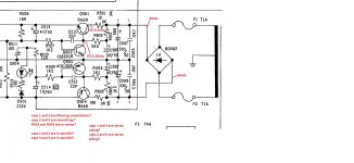
im not sure if i should have put this here or elsewhere,but as im learning i dont realy have anyone to advise if im doing things right so attached is a diagram with a hypathetical voltage from the rectifier.
i just need to know if i am on the right track or not, and if not how i should be looking at it
ive put question marks against what i need to know
many thanks
i just need to know if i am on the right track or not, and if not how i should be looking at it
ive put question marks against what i need to know
many thanks
Attachments
Simply put Poundy -
Series and Parallel Circuits - learn.sparkfun.com
Yes R501 & R502 are in series it allows filter capacitor C509 to function.
Series and Parallel Circuits - learn.sparkfun.com
Yes R501 & R502 are in series it allows filter capacitor C509 to function.
Caps 1 & 3 (and 2 & 4) are not in series because the common connection between them is the ground or 0 volt connection. They would be in series only if there was no other connection at the point where the two components join.
Caps 1 and 3 work much better at higher frequencies than the big electrolytic types. These little caps provided a low impedance (act like a short) to very high frequency AC. They also act as 'snubbers' across the bridge rectifier which can produce unwanted noise as the dioses come in and out of conduction.
Caps 2 and 4 are technically called 'reservoir caps' although smoothing cap is often used. These charge to peak value of the AC from the transformer. So if you had 30 volts DC here we could say the transformer would be a 21-0-21 vac type. Because the voltages are high we can discount rectifier losses in the calculation which is = Vdc/1.414 That gives the RMS AC voltage of the transformer.
The lower 30v is actually negative 30 volts, not positive.
The resistors are in series and this is done to provide a point to add more smoothing (C509) in order to generate a really clean bias supply for the regulator.
If you really had 0.3 and 0.28vdc as shown then you would have some real problems 😉
None of the caps are in series as far as we are concerned because of the common zero volt or ground line running in the centre. That point is our reference and divides the circuit into the upper positive section and the lower negative one.
Those resistors effectively feed the base of Q501 + collector of Q502 splitting them up just because there is a capacitance to earth being used as a filter which is not in series doesn't affect the combined VALUE of resistance feeding both those BJT,s .
Are you going to tell me when you get your meter out and measure the resistance it doesn't total up to the combined values ?
That is the practical and known meaning of two resistors in series ---combined value a filter using a capacitor to earth between then doesn't change ohms law.
Are you going to tell me when you get your meter out and measure the resistance it doesn't total up to the combined values ?
That is the practical and known meaning of two resistors in series ---combined value a filter using a capacitor to earth between then doesn't change ohms law.
R503 and R504 are probably for stability, allowing C511 and C512 to do their work. Otherwise they would be shorted to ground at AC at one end. Its not uncommon to see low value base and emitter resistors in a circuit to prevent unwanted RF oscillations. Unintended Colpitts oscillators can be formed by device ad other capacitances for instance.
Last edited:
Caps 1 and 3 work much better at higher frequencies than the big electrolytic types. These little caps provided a low impedance (act like a short) to very high frequency AC. They also act as 'snubbers' across the bridge rectifier which can produce unwanted noise as the dioses come in and out of conduction.
Caps 2 and 4 are technically called 'reservoir caps' although smoothing cap is often used. These charge to peak value of the AC from the transformer. So if you had 30 volts DC here we could say the transformer would be a 21-0-21 vac type. Because the voltages are high we can discount rectifier losses in the calculation which is = Vdc/1.414 That gives the RMS AC voltage of the transformer.
The lower 30v is actually negative 30 volts, not positive.
The resistors are in series and this is done to provide a point to add more smoothing (C509) in order to generate a really clean bias supply for the regulator.
If you really had 0.3 and 0.28vdc as shown then you would have some real problems 😉
None of the caps are in series as far as we are concerned because of the common zero volt or ground line running in the centre. That point is our reference and divides the circuit into the upper positive section and the lower negative one.
what i meant in my diagram was 0.3 and 0.28vdc voltage drops, i just wanted to see if i was making the right calculations, and i did mean to put a minus for the bottom voltage, just rushing before i went to work 🙁
So 0.3 volts across 10 would give a current draw of...... well you can tell us 🙂 and also see if you can work out the dissipation in the 10 ohm if there is 0.3 volts across it.
It is 0.03 but not milliamps. We work in ohms, volts and amps and so 0.3 volt across 10 ohms is 0.3/10 = 0.03 Amps.
We could also write that 0.03A is the same as 30 milliamps.
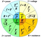
You might find this useful and you will see there are three ways of working the power dissipation out once you have all the numbers. Try it 🙂
We could also write that 0.03A is the same as 30 milliamps.
You might find this useful and you will see there are three ways of working the power dissipation out once you have all the numbers. Try it 🙂
Attachments
Thats a great tool thanks
so hopefully this is right
0.03a x 0.3v= 0.009w
0.3v2 / 10Ω = 0.009w
10Ω x 0.0009a =0.009w
so hopefully this is right
0.03a x 0.3v= 0.009w
0.3v2 / 10Ω = 0.009w
10Ω x 0.0009a =0.009w
its strange actualy, all the references i am reading(the art of electronics) etc and the course i am doing, only ever realy reference ma not Amps
10Ω x 0.0009a =0.009w
This one should be 10*(0.03 * 0.03)
It is watts = I squared multiplied by R
Edit... I see your 0.0009 was I squared 🙂
its strange actualy, all the references i am reading(the art of electronics) etc and the course i am doing, only ever realy reference ma not Amps
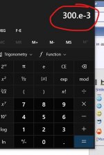
The basic units are always volts, ohms and amps. Once you get used to juggling them around you will start using smaller units automatically
So your W=I*V becomes 30E-3 * 300E-3 if you are using a scientific calculator. It is entered as 300 Exp 3 and then we use the minus sign to make it 300E-3
Attachments
Last one for today 🙂
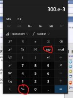
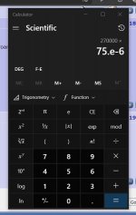
So can you calculate the voltage you would measure across a 270k resistor that has 75 microamps flowing through it.
I'll look in tomorrow...
So can you calculate the voltage you would measure across a 270k resistor that has 75 microamps flowing through it.
I'll look in tomorrow...
Erm... not quite 🙂
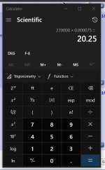
It should look like this.
270k is 270,000 ohms and 75uA is entered as 75E-6 on a scientific calculator. Once entered it expands out on this calculator to 0.000075
So we have 270,000 * 0.000075 giving 20.25 (volts)
It should look like this.
270k is 270,000 ohms and 75uA is entered as 75E-6 on a scientific calculator. Once entered it expands out on this calculator to 0.000075
So we have 270,000 * 0.000075 giving 20.25 (volts)
Attachments
- Home
- Amplifiers
- Solid State
- questions about items in a circuit