A couple of years back, I got bought a PCB from a Chech guy on ebay.
I did get it and all is fine as far as I can tell...but I have a few questions.
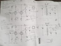
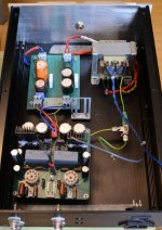
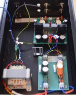
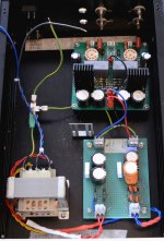
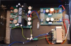
I'll post schematic and pics, in the hope that someone will shed some light on those questions.
1. There's a spot for a relay on the board, the model info for that is all well and good, except the relay comes in 5Vdc and a 12Vdc versions.
2. Having listened alot to tube gear, I don't really have much DIY experience in that area....So the question is what value volume attentuator to use?
I have 10K, 100K (quite a few), one 50K (currently in use in a headphone amp) and one regular log potentiometer @ 50K ALPS RK27.
EDIT: nevermind my notes on the schematic, I guessed at the value for the relay as it was the only I found at the time, I now know Farnell carries a 12V version as well.
I did get it and all is fine as far as I can tell...but I have a few questions.
I'll post schematic and pics, in the hope that someone will shed some light on those questions.
1. There's a spot for a relay on the board, the model info for that is all well and good, except the relay comes in 5Vdc and a 12Vdc versions.
2. Having listened alot to tube gear, I don't really have much DIY experience in that area....So the question is what value volume attentuator to use?
I have 10K, 100K (quite a few), one 50K (currently in use in a headphone amp) and one regular log potentiometer @ 50K ALPS RK27.
EDIT: nevermind my notes on the schematic, I guessed at the value for the relay as it was the only I found at the time, I now know Farnell carries a 12V version as well.
Attachments
Last edited:
On a casual glance a CC DC couple to a CF. I have one downstairs with ECC88 (6C23). This circuit has been used a zillion times with a zillion tubes. Frank’s 6SN8, Bottlehead foreplay for example.
Adding a CCS to the top of the CC and the bottom of the CF.
We used a 100k RS/Alps pot.
dave
Adding a CCS to the top of the CC and the bottom of the CF.
We used a 100k RS/Alps pot.
dave
Safety diodes are missing from that schematic... You might want to add them.
100k is pretty common.
100k is pretty common.
On a casual glance a CC DC couple to a CF. I have one downstairs with ECC88 (6C23). This circuit has been used a zillion times with a zillion tubes. Frank’s 6SN8, Bottlehead foreplay for example.
Adding a CCS to the top of the CC and the bottom of the CF.
We used a 100k RS/Alps pot.
dave
Thanks for the info!
Safety diodes are missing from that schematic... You might want to add them.
100k is pretty common.
What type of diode? Added where?
Thanks!
I'd use any 1kV 1A diode like 1N4007 or HER108.
Between the plate of the first tube and the cathode of the second.
Like in this picture:
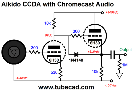
Between the plate of the first tube and the cathode of the second.
Like in this picture:
Member
Joined 2009
Paid Member
those diodes are hardly necessary, when the cathode is loaded on 10k,
I thought you had meant to add a reversed diode across emitter-collector of the power supply transistor to protect it from reverse bias at power down, depending on other factors of course
I thought you had meant to add a reversed diode across emitter-collector of the power supply transistor to protect it from reverse bias at power down, depending on other factors of course
I'd use any 1kV 1A diode like 1N4007 or HER108.
Between the plate of the first tube and the cathode of the second.
Like in this picture:
I see, that could most likely be done very easily on the bottom of the PCB.
Thanks again! Grately appreciated!
Once my daughter is old enought to stay away from things that can hurt her/she can hurt, I'll once again have tube power amplifier as well.
No clue as to the voltage to get when it comes to the relay? As I wrote, there are two versions of that model, a 5V and a 12V.
Member
Joined 2009
Paid Member
(6C23).
that’s a good substitute indeed, 6n23p
Edit: why does it look in the schematic as if the heaters are wired for 12V but the power supply to the regulator is labelled for 6V ? The 6n23p needs 6V if you want to try it.
The heater supply could be convenient for energizing the relay so pick a relay to match the heater voltage.
Last edited:
Member
Joined 2009
Paid Member
The diode is VERY necessary. Think what happens at power on, filament are cold and the first triode wont conduct, thus it's plats will be at B+.those diodes are hardly necessary, when the cathode is loaded on 10k,
I thought you had meant to add a reversed diode across emitter-collector of the power supply transistor to protect it from reverse bias at power down, depending on other factors of course
This voltage will be present between grid and cathode on triode 2 , it can even cause flash-over between grid and cathode.. The tube won't survive this.
I just recalled that there was supposed to be a power supply, relay-timer board designed for use with the preamp board.
The seller was out and the listing on ebay was for the preamp board only.
I did get the schematic and BOM for the other board though, as I just found out when I searched through some diy related papers.
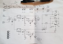
I'll post the Schematic first to see if I can get some further useful information from that(maybe fire up KiCad some soon and design the missing PCB myself....or if simple enough, just do it on perfboard).
The reason for not posting both the schematic and the BOM right now is that I don't know the rules about those things as it is not my design.
I can say as much as that the two regs in the schematic (IC1, IC2) are 7809's.
The seller was out and the listing on ebay was for the preamp board only.
I did get the schematic and BOM for the other board though, as I just found out when I searched through some diy related papers.
I'll post the Schematic first to see if I can get some further useful information from that(maybe fire up KiCad some soon and design the missing PCB myself....or if simple enough, just do it on perfboard).
The reason for not posting both the schematic and the BOM right now is that I don't know the rules about those things as it is not my design.
I can say as much as that the two regs in the schematic (IC1, IC2) are 7809's.
Attachments
those diodes are hardly necessary, when the cathode is loaded on 10k
I've had tubes arc over on start up without it using 22k resistors... It costs almost nothing to add... Just saying.
Member
Joined 2009
Paid Member
The diode is VERY necessary. Think what happens at power on, filament are cold and the first triode wont conduct, thus it's plats will be at B+.
This voltage will be present between grid and cathode on triode 2 , it can even cause flash-over between grid and cathode.. The tube won't survive this.
Yes, that’s what I’ve read too but I'm not convinced. There are many pre-amps (e.g. Kondo, Shindo, Audio Note) and power amps (Loftin-White style) that use this ‘common-cathode dc coupled to next grid’ topology without these diodes, some also used SS rectified supply. And I don’t read about their use of these diodes, neither do I see diodes in photos of these equipment. I’ve no axe to grind on their inclusion or not, it’s just that it seems to me that it’s like the popular B+ delay advice - unnecessary in most cases.
As usual, devil-in-the-details and if Koda and others observed nasty goings-on it makes sense to include them in a new or untried circuit or in a circuit proven to need them.
Last edited:
those diodes are hardly necessary, when the cathode is loaded on 10k,
I thought you had meant to add a reversed diode across emitter-collector of the power supply transistor to protect it from reverse bias at power down, depending on other factors of course
If one reads the tube data then it's clear that 50Volt is the maximum negative value for the grid refered to the cathode. Reason for this could be the very close distance between thr grid <> cathode for this tube.Yes, that’s what I’ve read too but I'm not convinced. There are many pre-amps (e.g. Kondo, Shindo, Audio Note) and power amps (Loftin-White style) that use this ‘common-cathode dc coupled to next grid’ topology without these diodes, some also used SS rectified supply. And I don’t read about their use of these diodes, neither do I see diodes in photos of these equipment. I’ve no axe to grind on their inclusion or not, it’s just that it seems to me that it’s like the popular B+ delay advice - unnecessary in most cases.
As usual, devil-in-the-details and if Koda and others observed nasty goings-on it makes sense to include them in a new or untried circuit or in a circuit proven to need them.
Other tubes has larger values, but protection preventing abnormal grid voltages is never wrong. The reason some ( lazy) designers omit them is no reason to follow their path.
https://frank.pocnet.net/sheets/030/e/ECC88.pdf
I've had tubes arc over on start up without it using 22k resistors... It costs almost nothing to add... Just saying.
Newbie question, in the olden days was an NE2 neon bulb ever used for this purpose as well? I have some surplus tone boards from a 1950's organ with a couple NE2 lamps on each board but they are not pilot lights. If so would that work as well as a diode or would it not be neutral enough?
NE2's were the classic answer. They work great, breaking into conduction about 60 - 75 Volts, or so.
I wouldn't use the muting relay as shown. The pull-down resistor should be always in circuit, and only the shorting contacts switched.
All good fortune,
Chris
I wouldn't use the muting relay as shown. The pull-down resistor should be always in circuit, and only the shorting contacts switched.
All good fortune,
Chris
I've also seen NE-2 used as part of the oscillator circuits in an old organ, too (each key had a couple of neons).
Member
Joined 2009
Paid Member
If one reads the tube data then it's clear that 50Volt is the maximum negative value for the grid refered to the cathode. Reason for this could be the very close distance between thr grid <> cathode for this tube.
Other tubes has larger values, but protection preventing abnormal grid voltages is never wrong. The reason some ( lazy) designers omit them is no reason to follow their path.
https://frank.pocnet.net/sheets/030/e/ECC88.pdf
I believe it’s not the max -Ve voltage you’re worried over, but a large +Ve voltage applied to the grid when the supply rail comes alive. I’ve never seen a +Ve limit quoted as a datasheet spec., but some do give a max grid dissipation limit.
Lazy designers, you don’t think that’s me? 🙂
I think lazy design also includes not understanding your circuit to decide what is needed and what is not needed.
Last edited:
- Home
- Amplifiers
- Tubes / Valves
- ECC88 PreAmp - Questions