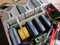
After 13 years of reliable and pleasing operation, my A75 started to make crackling sounds, faintly on the left but strongly on the right channel.
After replacing all caps except for the big cans - they measured like new - everything was ok for a few weeks, then the noises came back.
Now that i´ve replaced all trimmpots and started re-commisioning, on the first channel 2 output FETs (IRF630 by IR) have 2x resp. 3x more bias current than the other 10, whose currents are quite close.
On matching back then, the 12 N-FETs had 3,43-3,44V UGS at 180mA.
Now i´m wondering if this is normal MOSFET behaviour, aging, brand-dependent or whatever. So if anybody could share their experience, i´d be glad to hear.
Thanks
Norb
so serious hardware really calls for bigger mosfets
statically - OK, 6W per piece, but you didn't tell how they're stressed dynamically
statically - OK, 6W per piece, but you didn't tell how they're stressed dynamically
Ever since they are stressed by Isophon Europa, but luckily it does not sound like stress ... even my neighbors don´t think so. 🙂
Edit: ZM, do you have any recommendation for (obtainable) output devices ? A redesign would then make sense, since measuring the P-FETs on the down-side is exactly that.
Edit: ZM, do you have any recommendation for (obtainable) output devices ? A redesign would then make sense, since measuring the P-FETs on the down-side is exactly that.
Last edited:
if you want small ones, nothing wrong with IRF520/530/540//9520/9530/9540 ; these being 100V jobbies but we count that you are not going wild with swing
same numbers, just starting with 6 (instead of 5) for higher voltage
if going to biguns - IRFP240 & IRFP9140 are hard to beat
same numbers, just starting with 6 (instead of 5) for higher voltage
if going to biguns - IRFP240 & IRFP9140 are hard to beat
It´s loud enough, no worries about rail voltages: +/-39,8 VDC at 1,6A total bias current
If i remember correctly 630/9630 are TO220 version of orignal A75 IRF230/9230, they have similar gate charge/current capability etc. so thats why i used them.
240/9140 have double gate charge, with 12 devices in parallel i´m afraid it could affect sonic characteristic.
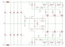
I fiddled around with A75 settings back then (folded cascode, feedback, ..) and found nice settings for me.
If i remember correctly 630/9630 are TO220 version of orignal A75 IRF230/9230, they have similar gate charge/current capability etc. so thats why i used them.
240/9140 have double gate charge, with 12 devices in parallel i´m afraid it could affect sonic characteristic.
I fiddled around with A75 settings back then (folded cascode, feedback, ..) and found nice settings for me.
Last edited:
BTW: I built F5 turbo V1 with 240/9140 few years ago (just saw i have about 20 each), it worked perfectly, but sometimes any one output FET always failed on power on after power off because of too high bias current, like some kind of thermal hysteresis, but i never managed to find a solution, so i sticked with my A75. Not bad either ...
It´s loud enough, no worries about rail voltages: +/-39,8 VDC at 1,6A total bias current
If i remember correctly 630/9630 are TO220 version of orignal A75 IRF230/9230, they have similar gate charge/current capability etc. so thats why i used them.
240/9140 have double gate charge, with 12 devices in parallel i´m afraid it could affect sonic characteristic.
I fiddled around with A75 settings back then (folded cascode, feedback, ..) and found nice settings for me.
you did it already, so no reason to not believe in your experience 🙂
with bigger case mosfets, you can go with half number vs. existing
just choose what's more convenient to you
Dear ZM, thanks for your answers so far, but may i once again try to tap your - or anybody`s - knowledge regarding:
If i´m boring, sorry for that, but i just cant suppress my german genes on this one, since my experience with MOSFETs so far is mostly digital:
switch or bang 😀
Norb said:Now i´m wondering if this is normal MOSFET behaviour, aging, brand-dependent or whatever
If i´m boring, sorry for that, but i just cant suppress my german genes on this one, since my experience with MOSFETs so far is mostly digital:
switch or bang 😀
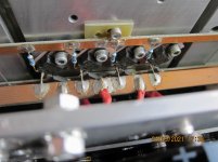
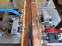
thermally induced aging, due to inadequacy of clamping arrangement
two factors:
- you have no split washers; that combined with
-plastic bushing, which is giving up with time, both in thickness and elasticity, so all that:
leads to lesser pressure of mosfet body to heatsink, thus increased temperature
been there, not done, but seen that
had one famous Japanese preamp (lazy to search for pics in PC to see which), exactly same arrangement
idiot ZM, got burned finger and blister, checking temp. of one of T0220, being on common heatsink with several same ones
then had some serious time spent on salvage operation
ha, I remember - Onkyo P200 ...... what a piece of Drek - Overambitious Underengineered Drek , let's just call it - veeeeerry expensive blanket over your speakers
genes - I owe some to my late Omama, so no biggie 🙂
Last edited:
noise, yes
elevated Iq with time .... even after resoldering ... that's overstressed part
though, I know that I'm still in Spielhosen, comparing to Pa

elevated Iq with time .... even after resoldering ... that's overstressed part
though, I know that I'm still in Spielhosen, comparing to Pa
Nelson Pass said:Most of the cases of this sort of noise I have seen are solder connections.
Checked/resoldered the frontend PCB and outputs, but found no visibly defective solder connections.
May i ask, Mr. Pass, which other things - apart from defective pots/trimmers - can lead to this noise ?
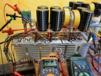
I did some kind of insulation measurement between output transistors and heatsink, shorted Gate, Drain and Source and applied 32VDC between them and heatsink, DMM showed a current fluctuating between 2mA and a few µA. Could this be a noise source too ?
Next step: sand/polish/deburr heatsink surface and replace all kapton insulators. 48 output devices - less is sometimes more 🙂

Zen Mod said:kapton is .......... I don't trust in kapton (Capton?)
have some problematic amps with Kapton, for repair, when I replaced it with mica & grease, all good
New kapton insulators on one channel, insulation test (53VDC) result: fluctuating current 10-80 µA.

Can´t believe i´m still too stupid to bolt TO220 to some aluminium - after 35 years of building electronics from RC-models to industrial dc power equipment - so i´m happy about your remarks.
Swapped kapton for silicone pads: 0.04 µA. No need to go crazy anymore ...

BTW: I built F5 turbo V1 with 240/9140 few years ago (just saw i have about 20 each), it worked perfectly, but sometimes any one output FET always failed on power on after power off because of too high bias current, like some kind of thermal hysteresis, but i never managed to find a solution, so i sticked with my A75. Not bad either ...
Thank you for sharing your experiences, norb! Would you expand on what happened with your F5 Turbo?
I built the F5T cascode version (+/- 32VDC supply) without current limiter and 2x 3 output devices (Vishay-Siliconix). I set it up, bias 700mA per device, and it worked, no problems so far.
When switching the amp on again some time after power off, one output FET branch would randomly go defective within seconds from too high bias current. After replacement the amp would work again, but on another power off->on cycle same thing happenend.
Could have added the current limiter circuitry or DC-monitoring, but felt uncomfortable about connecting this amp to my speakers, not to mention the prospective of output device replacement once a day.
Still have a Pumpkin Preamp, i may use the F5 hardware for a ZenMod-tweaked F4 some day. Having seen my F5T photos again, i am glad i have made advances in output device mounting since A75-days. Long live the Jester 🙂
Attachments
- Home
- Amplifiers
- Pass Labs
- Output Mosfets on A75