I have a signal generator which has good distortion performance but suffers from 50 Hz hum when measuring THD + Noise. With a 400 Hz filter the measured residual noise floor is much lower.
I think this is because it has a E-I power transformer in the case just cms from the oscillator and amplifier circuitry.
I want to relocate the transformer to outside the case and build a new regulator Pcb to go where it was.
The existing regulator circuitry is on the existing power amp board and can readily be bypassed.
The only issue is that the power supply is about 50v (unregulated) in and 37v (regulated) out which I believe is out of the range of a LM317/LT3045 type IC or. Jung type super regulator.
The generator, having a class AB power amplifier output stage, is best suited to a series regulator, rather than a shunt which suits constant current type device more, if I have that correct?
If that seems reasonable I would be grateful for recommendations on a IC or discrete low noise design for this project.
With thanks,
Attachments
Last edited:
Take a look at the high voltage version of the LM317
https://www.ti.com/lit/ds/symlink/lm317hv.pdf?ts=1621690311636
https://www.ti.com/lit/ds/symlink/lm317hv.pdf?ts=1621690311636
Sorry, I posted this in the wrong place, could I ask that a moderator move it to "Equipment & tools" please?
A series regulator will be fine. This should work, and has a maximum of 125V and 700mA.
https://www.ti.com/lit/ds/symlink/tl783.pdf?ts=1621716984775&ref_url=https%3A%2F%2Fwww.google.com%2F
https://www.ti.com/lit/ds/symlink/tl783.pdf?ts=1621716984775&ref_url=https%3A%2F%2Fwww.google.com%2F
Last edited:
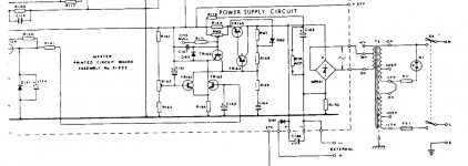
Thanks all, I am a little worried whether a LM317HV would be low noise enough, I posted a schematic of the existing regulator into the first post, as a vastly more experienced member described the existing power supply as a "work in progress" in the repair thread I posted.
Should i bypass the existing PSU or just use the LM317HV as a pregulator?
Should i bypass the existing PSU or just use the LM317HV as a pregulator?
You can always use an RC filter after any regulator circuit to lower noise.
Of course it will raise the output impedance at lower frequencies.
Of course it will raise the output impedance at lower frequencies.
Thanks Ray, I've become a fan of RC filters before regulators in line-level audio work since downloading PSU designer and learning to how to calculate them properly for load.
I was planning on swapping the existing 1000uf filter capacitor for a 2200uf/10Ohm/2200uf bank with a snubber to hopefully reduce the amount of HF noise the regulator has to deal with.
I don't know much about power supply output impedance apart from that lower is better, doesn't seem like a good trade to me?
Could you point me to some more information or explain the consequences further please?
With an LM317HV, you can decouple the ADJ pin to ground to reduce the noise gain to unity. No idea if it's good enough, as I don't know what the requirements are.
How much current? You’ll incinerate most linear regulators with 13V across them if you’re powering anything requiring much current.
This is another HV option if it meets your requirements: TPS7A4001 data sheet, product information and support | TI.com
This is another HV option if it meets your requirements: TPS7A4001 data sheet, product information and support | TI.com
Thanks Marcel, the requirements are to power the signal generator as per this thread:
Gould J3B signal generator repair help
I should guess 37V at 1-1.5 amps.
Gould J3B signal generator repair help
I should guess 37V at 1-1.5 amps.
Thanks Marcel, the requirements are to power the signal generator as per this thread:
Gould J3B signal generator repair help
I should guess 37V at 1-1.5 amps.
13 V drop at 1.5 A is almost 20 W dissipated in the regulator. This isn’t going to work. I’d look into a buck regulator or external SMPS.
Fair enough, Im not sure how to go about working out the power consumption but the thing is meant to put out something like 3W from it's low-Z output and 1.5W from it's 600Ohm balanced output at the same time along with whateve the square wave generator section puts out.
The existing pass transistor is a 2n5296, so fairly beefy
https://www.mouser.com/datasheet/2/68/2n5294-1368145.pdf
What sort of figure would seem reasonable?
The existing pass transistor is a 2n5296, so fairly beefy
https://www.mouser.com/datasheet/2/68/2n5294-1368145.pdf
What sort of figure would seem reasonable?
I would look at how everything is grounded. I can’t imagine a piece of test equipment that was sold with 50hz interference.
...Gould J3B signal generator repair help
I should guess 37V at 1-1.5 amps.
The manual clearly says 40-48V, 250mA, applied at the back terminal sockets provided.
Attachments
The manual clearly says 40-48V, 250mA, applied at the back terminal sockets provided.
How silly of me, thank you! 😀
I should like a little more headroom if at all possible, perhaps say a supply circuit capable of supplying 500ma that runs cooler in the case.
I’m also not sure how the low Z output is meant to supply around an amp maximum in that case?
TL783 has slightly better rejection than the LM317
Thanks for the recommendation, I shall look it up.
"I think this is because it has a E-I power transformer in the case just cms from the oscillator and amplifier circuitry.
I want to relocate the transformer to outside the case and build a new regulator Pcb to go where it was"
Hi, If you are comfortable about safely working with AC mains - Why not temporarily take the mains transformer out and wire it up from a metre away, that way you can prove or disprove if its the mains transformer causing hum magnetically.
If it is the mains transformer you could consider replacing it with a toroidal transformer. The toroid could have a lower AC output of 30 VAC and still give you the regulated 37 VDC.
If its not have a look at the smoothing capacitors and check that the Earthing (Ground Return) connections are OK. Earth loop can cause hum issue even for a Signal Generator.
13 V drop at 1.5 A is almost 20 W dissipated in the regulator. This isn’t going to work. I’d look into a buck regulator or external SMPS.
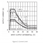
An LM317HV in TO-220 package on a large enough heatsink should typically be able to handle it, but only just. A current limit of at least 1.5 A is guaranteed up to 15 V voltage difference, typically it's >= 1.5 A up to about 18 V to 19 V.
LM317HV datasheet | TI.com
500 mA shouldn't be an issue at all for an LM317HV with a good heatsink.
The TL783 actually requires a lot of voltage; the line regulation is specified with at least 20 V between input and output, although typically the drop-out voltage is 10 V to 14 V depending on temperature at 500 mA.
TL783 datasheet | TI.com
Attachments
Last edited:
- Home
- Amplifiers
- Power Supplies
- IC/discrete regulator recommendation