The circuit you attached - I would be looking at the capacitors C161, C162, C163 and C164. Looks like C164 is the main smoothing capacitor.
From other note an external supply would only need to supply 250mA. I would expect C164 to be at least 1000uF 63V even 2200uF at 63V.
Don't really see the point replacing that circuit with a linear regulator, if its working properly it will be fine and will work for a long time.
These kinds of supplies were often built with unusually high AC secondary voltages, because in days gone by the mains line voltage was not so reliable or they wanted to sell the instrument overseas.
A physically small toroidal transformer specified at 30 Volts RMS AC at full load and rated at say at least 30 Watts should do OK.
So 30 VAC - 1.2 Volts =28.8 V x 1.414 = 40.7 V DC giving at least three volts for the power supply circuit.
Smoothing capacitor 2200uF at 63 V
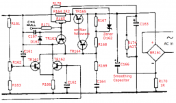
The power supply is hard to read but so some guesswork:-
C164 the main smoothing capacitor (probably mounted off the PCB). R170 is a current sense resistor, rapid current increases coupled through C163 to current limit, slow current increase beyond threshold sensed via R174 (AOT resistor). Current limit threshold set by preset pot R145, Voltage output set by preset pot R142.
There is an external signal to the base of TR142 probably to turn the supply off and look like C142 is for a slow startup.
I would look at how everything is grounded. I can’t imagine a piece of test equipment that was sold with 50hz interference.
It’s a strange one.
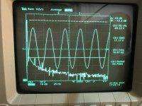
It shows up only at the extreme bottom end of the frequency capability of the set, this is the 10Hz FFT showing that a 50hz signal is almost 45 db lower than the fundamental.
Attachments
Thank you for your detailed notes Rich, very much appreciated.
As you guessed the main smoothing capacitor is off board and I have already replaced it with one of 2200uf and 80v. Even that is too small for the clamp and space provided and I ah e been eyeing some 4700uf 63v caps which would fit perfectly...
I wonder if it is current limiting which is causing the 50 hz breakthrough at low frequencies?
have a look at the power supply output on your scope, see if there is any ripple
you could measure the current being supplied by the power supply by the 37V line, should be less than 250mA DC.
you could look at the amount of 100Hz ripple on the smoothing capacitor, with a maximum current of 250mA the amount of 100Hz ripple there should be very small, that's a clue! ripple coming from the power supply would be 100Hz not 50Hz
if the smoothing capacitor ripple really is 50Hz then your bridge rectifier BR161 has a failed diode
if the 50Hz is coming from elsewhere some kind of earth loop or magnetically from the transformer (bit unlikely) try actually listening to the sig gen output via a speaker or headphones, might give you a clue if alter something such as earth connection etc
see attached might help to work out how the power supply works if you want to do that
anyways be careful, take care, stay safe, going anywhere near mains voltages can be a risky business
Attachments

How silly of me, thank you! 😀
....not sure how the low Z output is meant to supply around an amp maximum in that case?
The lo-Z out is transformer coupled. You can't determine the DC demand from the AC specs without going through the transformer ratio (unknown?).
I would take the word of Gould's engineers at face value. Not arbitrarily double it. This isn't a subwoofer. There's no "surprise!" signals.
have a look at the power supply output on your scope, see if there is any ripple
anyways be careful, take care, stay safe, going anywhere near mains voltages can be a risky business
Good point about the ripple frequency, I probed the regulated voltage output and found about 7mv of ripple, at the 1Khz the generator set to.
I am very careful around mains electricity, its a hobby after all and i dont want to zap myself. 🙂
The lo-Z out is transformer coupled. You can't determine the DC demand from the AC specs without going through the transformer ratio (unknown?).
I would take the word of Gould's engineers at face value. Not arbitrarily double it. This isn't a subwoofer. There's no "surprise!" signals.
Thanks PRR, I hadn't appreciated that the low-Z output was transformer coupled; I thought only the 600 Ohm balanced output was transformer coupled.
The only reason I am erring on the side of a larger supply is that the generator seems to sag with a 4ohm load at low frequency.
It's fine at, say, 100Hz and above but at it's 10Hz lower limit turning it up all the way trips the current limiter and the thing restarts.
I was hoping that with the beefier output transistors I have fitted (BD139/140) to replace the mismatched, slower and lower current non-originals already in it I an beef up the power supply section a bit and then try and set the current limiter a bit less aggressively to stop it from happening.
At the moment I get a full 2.83Vrms ( a handy figure to have for speaker testing, which is what I use this set for mainly) from 100Khz down to about 40Hz, I would like it to extend all the way down to 10Hz if at all possible.
hard to beef up or modify that Gould circuit, it looks well designed, perhaps look for some kind of fault that's drawing too much current from the power supply, are you sure that what you are asking of the sig gen is within Gould's spec
- Home
- Amplifiers
- Power Supplies
- IC/discrete regulator recommendation