This is oscillation caused by the Bias circuit of my first Luminaria. LT431 + 220u (SILMIC II) + 22u between Ref and Cathode.I eliminated the small capacitor and lowered the output to 22u. Then everything worked perfectly.

analog_sa and claudio52, I have actually thought about raising the gate resistor value and lowering the capacitor at the output of the LM337 bias supply regulator. Right now I have only 22R at the gate and I will try 100R or even higher. At the bias supply I have 220uF and I will try 10uF.
When I built the 2SJ28 choke loaded L'Amp a few years ago, one channel also had oscillation as I increased the bias. I changed the bias supply and that stopped the oscillation.
Thanks for the suggestions. I will work on it this weekend.
When I built the 2SJ28 choke loaded L'Amp a few years ago, one channel also had oscillation as I increased the bias. I changed the bias supply and that stopped the oscillation.
Thanks for the suggestions. I will work on it this weekend.
I don't believe your bias supply is misbehaving. Presumably you have a 10k or larger resistor decoupling it from the gate so there is no way the small additional capacitance of the zener can provoke instability in the bias supply.
The problem is fixed. I changed the Nichicon 220uF 25V capacitor at the output of the LM337 to a cheap no-name 22uF 16V and it now works with the zener installed. I ended up putting two 9.1V zeners in series.
The Nichicon's measured ESR was 0.5R and the no name cap's measured ESR was 2.6R, measurements done with a multi-function tester. The LM337 is apparently finicky about the ESR of the output capacitor. The TI data sheet does not mention this but the ON Semiconductor data sheet has this :
"An output capacitance (CO) in the form of a 1.0 F
tantalum or 10 F aluminum electrolytic capacitor is
required for stability. Using the classical tantalum or
aluminum electrolytic capacitor types with non−reduced
ESR (Equivalent Series Resistance) value is necessary.
Low−ESR or similar capacitor types with reduced ESR
value and ceramic capacitors can cause instability or
continuous oscillations in the application."
LM337 from TI has a different stability characteristics compared to others as discussed in D-Noizator: a magic active noise canceller to retrofit & upgrade any 317-based V.Reg. staring at post1534. All LM317 is much better noise and stability-wise.
Thanks for the information.
I have the ST Micro LM337, which was noted as unstable in post 1534. The problem that I encountered also points to it being unstable under certain conditions.
I have the ST Micro LM337, which was noted as unstable in post 1534. The problem that I encountered also points to it being unstable under certain conditions.
Have to admit i am really surprised. Any idea how the presence of the zener induces instability?
No, I don't have any idea at all. It's beyond my diyer level of technical understanding.
On another note, I just bought a 2SK180 from watanabetomoaki to replace the one in the left channel that has the huge amount of gate leakage current. I hope the new one will be better. The right channel's 2SK180 isn't as bad so I can live with it.
On another note, I just bought a 2SK180 from watanabetomoaki to replace the one in the left channel that has the huge amount of gate leakage current. I hope the new one will be better. The right channel's 2SK180 isn't as bad so I can live with it.
...I might have a couple of options for a driver stage as I have been following up on the capabilities of the 2P29L tube preamp I'm building (using the Bartola Mu Follower 'Gyrator' schematic). I am trying to get my head around the maths to calculate the output impedance but I'm told that Zout for the Bartola genre preamps is typically well under the 75ohms you mentioned previously. Maths isn't one of my strengths so it's taking a bit of effort!
I finally worked out that Zout of the preamp is around 34ohms, so looking good...
Just need to finish it now.
Instead of a zener, you can use a TL431.Have to admit i am really surprised. Any idea how the presence of the zener induces instability?
But that soes not solve it totally.
In the past I made some (semi-)high voltage shunts: a TL431 stacked/cascoded with a EL84 for 350V and IRF130 for 120 volt. The latter was unstable. I pinpointed it back to the resistors I used, even with a cap across the top divider there was instability. For instance. I used Corning glass metal foil (English) of which I bought several boxes of 100; they were very bad, hysteresis. I had noticed years ago that the Corning behaved bad but never saw it so clear. A friend who had also bought a box of these called me - did you notice something weird with these resistors?
Anyway, in old Philips development documentation they say feedback resistors need to be special quality, high power, so they do not have small increases with the signal of temperature. That could be the cause. Carbon was OK.
The the decoupling across the divider is also of importance.
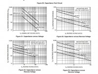
And the total Cak is of importance roo, the specs have a graph.
Note that the TL431 without a A/K capacitor is also stable . . .
Last edited:
Ben, have you done distortion analysis of the 2SK180-choked amplifier?
In my sims I found that, as expected, with 0.7V (-8.4 db):
At the higher voltage, amplification is higher with 4 dB.
So the nice thing is, that it looks as if the amplifier 'behaves' better at 24 volts! There is less difference.

I also saw: The 2SK182 is about 6dB more lineair. But as voltage in increased, the distortion of 2SK180 starts to look like a 2SK182 running at a lower voltage. Not unexpected, that is.
Other question: Pass says in the ACA design, that the harmonics will be percieved different with plugging in in phase or not. Have you noticed?
In my sims I found that, as expected, with 0.7V (-8.4 db):
- as current is reduced in general, distortion increases.
- instead of 2.5A @ 24Vb, 1.8Amp, dist H2 goes from -41 to -44. But H3 stays the same, -63 dB
- I noted that at 60Vb, distortion is lower than at 24 Vb. Going from 1.6Amp to 1 amp, H2 dist goes from -46 to -51 but H3 goes up from -73 to -63.
- instead of 2.5A @ 24Vb, 1.8Amp, dist H2 goes from -41 to -44. But H3 stays the same, -63 dB
- I noted that at 60Vb, distortion is lower than at 24 Vb. Going from 1.6Amp to 1 amp, H2 dist goes from -46 to -51 but H3 goes up from -73 to -63.
At the higher voltage, amplification is higher with 4 dB.
So the nice thing is, that it looks as if the amplifier 'behaves' better at 24 volts! There is less difference.
At 2 volts in (LTspice, = 0dB in panel) the 24 volt version goes to H2 -37, H3 -44 while in the 60Vb version H2 goes to -42 and H3 to -49dB, so third harmonics increases quickly.
This means that listening to the 24V version might be more stable in practice. Counterintuitive. I also saw: The 2SK182 is about 6dB more lineair. But as voltage in increased, the distortion of 2SK180 starts to look like a 2SK182 running at a lower voltage. Not unexpected, that is.
Other question: Pass says in the ACA design, that the harmonics will be percieved different with plugging in in phase or not. Have you noticed?
Instead of a zener, you can use a TL431.
Are we talking about the same? The protection zener at the gate?
I also saw: The 2SK182 is about 6dB more lineair.
From sims? I would not put much trust into that. The distortion level of different samples of the same type differs easily by 6db.
No way to know how representative for each SIT was the physical data the model was based upon.
Are we talking about the same? The protection zener at the gate?
A yes. You are so right. I am wrong, associating it with stabilizing

I’ll see in practice. Will take some time though. I have an analogue dist meter 🙂From sims? I would not put much trust into that. The distortion level of different samples of the same type differs easily by 6db.
No way to know how representative for each SIT was the physical data the model was based upon.
triode_al,
As analog_sa said, LTSpice simulations do not always give distortion results that can be replicated in real life, and also there is variation in samples of Tokin SITs in real life. So simulations can not be relied upon to give accurate distortion predictions. I use LTSpice to check that a circuit will work reasonably well and then build, test, and tweak.
I did that with the common source version, trying out various voltage and current operating points.
With both the common source and common drain versions, I also measured distortion.
All of this is posted throughout this thread, so if you look at the older posts you will see what I did and measured.
In my search for a good operating point I did find that Vds of about 35V was a good place. That worked well for me as I wanted to take advantage of the higher power dissipation of the Tokins and get a higher power output.
As for distortion measurements, I use an USB sound card (Focusrite) and software (REW) and it is a very cost effective and easy to use, and the results are more than good enough for diy purposes. It's a great time for diyers now with the abundunce of available information on the internet and the availability of testing and measuring equipment at low prices compared to the old analog days.
I have noticed difference in sound when I reversed speaker connections, especially with my BAF2015 THF-51S amplifier. One way, the sound is more behind the speakers and the other way the sound projects more out in front of the speakers.
Last edited:
Another step towards a build today, managed to pick up a substantial heatsink for a good price. I'm not sure of the specific rating but it's about 45cm tall, 33cms wide and 5cms deep so I'm thinking that it should be adequate to mount and cool a pair (for stereo) of the Tokin devices.
On the question of mounting the Tokins I've read that ceramic insualtor/spacers are the way to go or is there a better way?
CERAMIC TRANSISTOR HEATSINK INSULATORS 2mm Size TO-3 SIZE | eBay
Sorry for the basic questions but I'm a newbie to this technology.
On the question of mounting the Tokins I've read that ceramic insualtor/spacers are the way to go or is there a better way?
CERAMIC TRANSISTOR HEATSINK INSULATORS 2mm Size TO-3 SIZE | eBay
Sorry for the basic questions but I'm a newbie to this technology.
In my search for a good operating point I did find that Vds of about 35V was a good place.
Ben, have you examined lower Vds at a higher current? Wondering if there is a lower voltage sweet spot at around 5A. Looks like i don't have two matching transformers to experiment with this.
I've read that ceramic insualtor/spacers are the way to go or is there a better way?
Your link is for TO3 spacers and none of the Tokins are TO3. Chances of finding suitable ceramics are slim. Keratherm is easily available and can fit any footprint.
- Home
- Amplifiers
- Pass Labs
- 25W Single Ended Hammond 193V Choke Loaded 2SK180 L'Amp