The 260VCT is a secondary, not a primary.
Mains is 120V, which should work in the US.
First, thanks!
I measured 7 ohms between the red wires.
I thought the greatest resistance was typically in the primary.
Also this is supposed to deliver 120-0-120 to a PCB, how?
That is 120V AC line input on the two RED wires.
Winding resistance depends on both the wire gauge and length for that winding.
Gauge depends on the current rating needed for that secondary.
There are also other windings on that core, so the brown-black-brown secondary winding
must have less current capability than the primary, and has a smaller gauge and higher resistance.
The black wire is the center tap of the brown/brown winding. Each red wire feeds a diode rectifier,
and the black wire is grounded. This makes a full wave rectifier.
Last edited:
That's 120V AC line input on the two RED wires.
Winding resistance depends on both the wire gauge and length for that winding.
Gauge depends on the current rating needed.
There are also other windings on that core. so the brown-black-brown secondary winding
must have less current capability than the primary, so a smaller gauge, and higher resistance.
Thanks! I agree because that’s the only thing that makes sense.
Also, I think the marking on the PCB is incorrect. It should be 130-0-130 instead of 120-0-120, because that’s also the only thing that makes sense.
This is basically a step-up transformer, so the primary will typically have lower resistance than secondary.
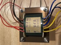
It's a 120 to 260VCT and 690VCT.
It's a 120 to 260VCT and 690VCT.
I think the marking on the PCB is incorrect. It should be 130-0-130 instead of 120-0-120
Sounds right, if that transformer came with the board.
Unless it's actually the transformer that should be marked 120-0-120.
This is basically a step-up transformer, so the primary will typically have lower resistance than secondary.
It's a 120 to 260VCT and 690VCT.
That tripped me at first too, I read 345-0-345 at the bottom. But it’s in fact 3.15-0-3.15.
This is basically a step-up transformer, so the primary will typically have lower resistance than secondary.
It's a 120 to 260VCT and 690VCT.
Sounds right, if that transformer came with the board.
Unless it's actually the transformer that should be marked 120-0-120.
That’s a very good point.
That tripped me at first too, I read 345-0-345 at the bottom. But it’s in fact 3.15-0-3.15.
That's a center-tapped 6.3V AC filament winding.
- Home
- Amplifiers
- Power Supplies
- Power transformer identification