I tried a dozen small and inexpensive toroidal transformers, mostly 115+115/6+6V, in the 10VA to 50VA range, on a low power amplifier. A few are good enough to work as output transformer, even in a single ended configuration. No difference on performance compared to a real output transformer. But most of them have a narrow bandwith even at low power. I wonder what the difference could be, and if there is a way to find out which transformer would work best before purchasing and testing it. As next test, I will probably try tubelab's suggestion: get a insulation transformer, connect all the winding in series (the best permutation to be tested experimentally), then add a few turns to make a secundary. The 200VA 4x115V RS stock number 117-6060 should need 40 turns to reflect 7K on the primary for a 4 ohm load. This transformer is abot the same size as the 40W Toroidy TTG KT88SE, but half the price.
May I suggest that what you could be witnessing is the winding direction I mentioned earlier. With the same transformer I found if you wired the primaries in one direction you would get good response from 10hz past 20khz with very little peaking. If you then wired the primaries in the other direction the bottom end fell off rapidly below 50hz with significant waveform distortion, out at the top end the response fell off beyond 10khz and then peaked out at 50khz to over 6db higher than the main range. What I was witnessing was massive high frequency ringing which was saturating the core and killing the inductance.
The ringing orientation was very fatiguing to listen to.
The primaries are wound bifilar in a single overlapping coil - so one end is close to the core and the other is insulated from it. One orientation seems to have much higher parasitics which was causing the ringing.
This is just my personal experience and seem fairly consistent across most of the toroidals I have tried.
Shoog
What power would you be aiming for ? That would give about 25-30W in my estimation. If you want less then something smaller.
Shoog
Think about what it was designed for. 6 volts at 4 ohms equals 9 watts. That would have 230 volts on the primary, which is what it was designed for. You would be able to push the peak voltage higher until you exceed current ratings or it saturates, but the low frequency limit of the transformer (set by primary inductance) will creep up. You know you’re ok to 50 Hz at 9 watts, but beyond that requires testing.
All my experience is at very low powers, 5watts tops so I defer to your superior knowledge.
Shoog
Shoog
Attached is a spreadsheet to work out impedance and maximum power output based on primary and secondary voltages vs frequency. Also attached is frequency response at 10W for an amp I built using power toroid outputs. Could be better but I was fairly aggressive on the compensation for the negative feedback.
tikiroo very appreciative of this Excel tool!
I thought I'd start with a cheap transformer. I found an Antek 115:15 V 10 VA transformer at $10 each ($40 if I use 4 of them for stereo in pairs). It is a small unit 2.5 inches by 1 inch, perfect for a small very compact amp.
Here is what I got (hope I did it right) if I put the primaries in series for 460 V:
28Hz @ 8.5 W in class A! 8 ohm secondary 6.8K primary. Might work for a small 6AQ5 bedroom amp held to class A?
View attachment 949065
Eh? With a 5k primary it will saturate at about 10 watts 50Hz...That would give about 25-30W in my estimation. If you want less then something smaller.
Again if your aiming for 5K your really not designing for what you have. 1.5-3K is the optimum range for these. Very few candidates fit the bill but those that do will not fight you in getting good results. Lets repeat this 6AS7 and EL86 are ideal candidates. As suggested series connecting two will increase your options significantly. I thought about that but never got round to trying it.
If manufacturers supplied the data for their products then you could calculate everything out but these parameters are not important for their intended purpose so its really a case of suck it and see what works.
Shoog
If manufacturers supplied the data for their products then you could calculate everything out but these parameters are not important for their intended purpose so its really a case of suck it and see what works.
Shoog
Last edited:
Windcrest, that looks about right as far as the transformer goes, I'd have to see loadlines to see whether those conditions will give you the power you are after. The primary current will be higher than what the transformers were designed for but should be OK at those low powers.
What power would you be aiming for ? That would give about 25-30W in my estimation. If you want less then something smaller.
I'd be happy with 8W per channel in class A, honestly. I figure that's attainable with PP EL86-triodes.
Antek makes a 50VA version. https://www.antekinc.com/content/AS-0506.pdf - It weighs only 2 lbs each, costs $17.50 each.
There's also a 25VA version, only $11 each and weighs only 1.3 lbs. https://www.antekinc.com/content/AN-02XX.pdf
Once you're down to the 50VA and 25VA toroids, there are 7V secondaries available too (3.57k ohm primary load according to the spreadsheet).
--
I would choose the 25VA for that power target. EL86 Class A PP is an excellent sounding amp in my experience, I picked up a quad of telefunkens for about €25.00 which makes it very cheap overall. Its also quite easy to add or take off secondary windings to fine tune your ratio - its about 10 windings per volt if I remember correctly.
Shoog
Shoog
Last edited:
Sounds good. I guess I'd aim for the 'sweet spot' of a 3.5k load, so I'd choose a couple of the 230V:7V 25VA ones. $22 plus tax and shipping. There's a cheap experiment for ya.
I already have a bunch of 6P43P, which I understand work well wired triode with 250V plate-cathode.
--
I already have a bunch of 6P43P, which I understand work well wired triode with 250V plate-cathode.
--
I remain skeptical of this, but would love to be proved wrong!As an example a typical power toroidal will outperform an Edcor any day of the week.
I thought I'd start with a cheap transformer. I found an Antek 115:15 V 10 VA transformer at $10 each ($40 if I use 4 of them for stereo in pairs). It is a small unit 2.5 inches by 1 inch, perfect for a small very compact amp.
Here is what I got (hope I did it right) if I put the primaries in series for 460 V:
28Hz @ 8.5 W in class A! 8 ohm secondary 6.8K primary. Might work for a small 6AQ5 bedroom amp held to class A?
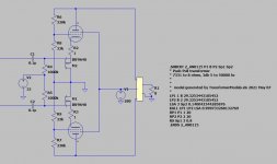
A PP "Unset" configuration with 6AQ5s would work well with these. The source impedance is low and you don't get the power loss you would with triode connection. The attached schematic gives 8W in Class A to below 30Hz with 2 x series connected AN-0115. Output impedance ~7 ohms with no global nfb. You'll have to come up with the front end yourself 🙂.
Attachments
As above ^^^ though I prefer 6V6 a likes to the 6AQ5, better power, better cooling, same internals, near enough at least. (Unless I've confused either another SN)
I have used some toroids in different ratios for a small SE amp of flea watts and have mixed experience.
A couple of scramble wound 30VA toroids that had the right voltage ratio, thereabouts, performed awfully. Woefully poor LF below 1kHz, driven with a 5k to 10k source.
Eventually I found some that were small enough VA to work, in what was a headphone amplifier.
The best configuration, in bench testing, was using a small 3VA toroid for a 100mW amp.
Oddly, I found to make the frequency response acceptable, and flat to 20kHz, instead of using both secondaries in parallel, for the correct impedance, I used one only, and left the other secondary floating.
I still havent run it enough to totally understand why this had an impact, but does not on other toroids, or what is 'different' in these particular ones.
I have a couple of spares and suspect they may be different in winding layout, or core to most toroids, due to their nature as small PC mount PTs.
Maybe I should get the cutter and crack one open...
Course, I should mention that it's a parafeed amp, but the bench test, did not include Parafeed cap.
I have the graphs and zplotter excel sheet somewhere
Last edited:
A PP "Unset" configuration with 6AQ5s would work well with these. The source impedance is low and you don't get the power loss you would with triode connection. The attached schematic gives 8W in Class A to below 30Hz with 2 x series connected AN-0115. Output impedance ~7 ohms with no global nfb. You'll have to come up with the front end yourself 🙂.
Awesome! I really have to find the time learn LT Spice someday (after retirement). I really appreciate this tikiroo. I've been wanting to use 6AQ5 in a small bedroom amp for a while now. Like in a small footprint tower chassis (a two story) so it avoids all the bedroom dresser clutter and still leaves my wife with space on the dresser, because its taller not wider (portrait style).
This simulation is going straight into my next breadboarding effort. I think it should be easy to drive 6AQ5 with any number of the proven line amp threads here ("Salas 6V6", "just another 12B4 line amp", there are a number of fine 6SN7 direct coupled line amps here too grounded-cathode-direct-to-cathode-follower types, etc...). Or maybe I'll just use the same front end from the 6BQ5 John Broskie amp I am making a PCB for now, the front-end of this one:
Unexpectedly good EL84 amp
Last edited:
You need a voltage amp and phase splitter to supply about 20Vrms to each half, lots of options to do that. Be sure to connect the primary windings like in Post #4. For 15V secondaries all the windings would be in parallel for an "8 ohm" load, but if you got 5V secondaries there are various series/parallel arrangements to allow for different loads. Just like the old transformers with 4 x 1 ohm windings that allowed 1,4,~8 and 16 ohm connections.
Of course some experimentation will likely be involved, as per Shoogs and Mondgenerators observations.
Of course some experimentation will likely be involved, as per Shoogs and Mondgenerators observations.
I'm the OP so not hijacking the thread... this is somewhat related but as a possible solution for sourcing heavier SE Transformers by sawing air gaps into a PP transformer...
clipped from VTV article:

clipped from VTV article:
Typical optimal gap size is paper thin (3 to 6 mils on imperial units). I don't know any simple tool capable to cut an already assembled transformer with this kind of precision. It is already difficult to make the same gap size on both right and left channel transformers by arranging the E-I laminations in the same orientation. The crude modification described on VTV will probably give a sub-optimal result, and different gaps on right and left channel transformers.
- Home
- Amplifiers
- Tubes / Valves
- Newbie question: Design techniques for using power toroid as OPT