Some recent threads on a Swedish forum has triggered me to evolve SLAM! into a SALS?A!
SALS?A! stands for Solhaga's AMT Line Source? Absolutely! and is a 220 cm long line source made of stacked broadband AMTs.
To just stack three SLAM! in a MTMMTMMTM configuration would be very costly as there's two magnets per centimeter and each magnet is €5.
So a weaker motor with one magnets standing instead of SLAM!s double laying magnets, would yield half a magnet per centimeter.
That is, only €500 worth of magnets for a full line source sized speaker.
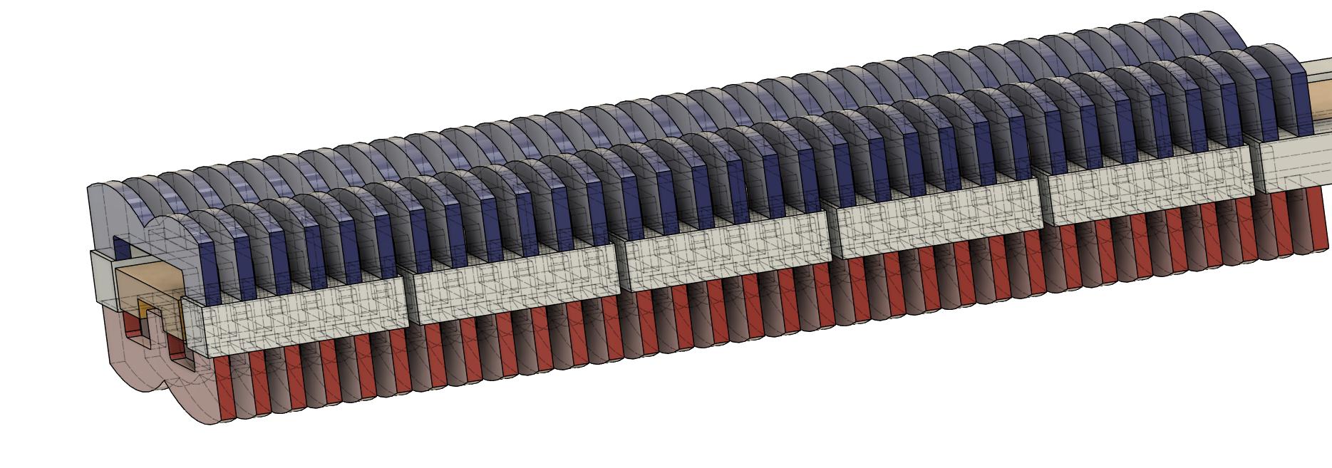
Here's a first draft of the motor:
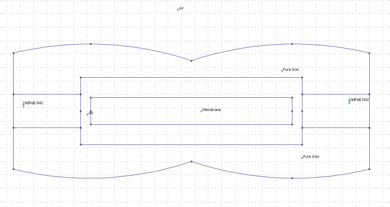
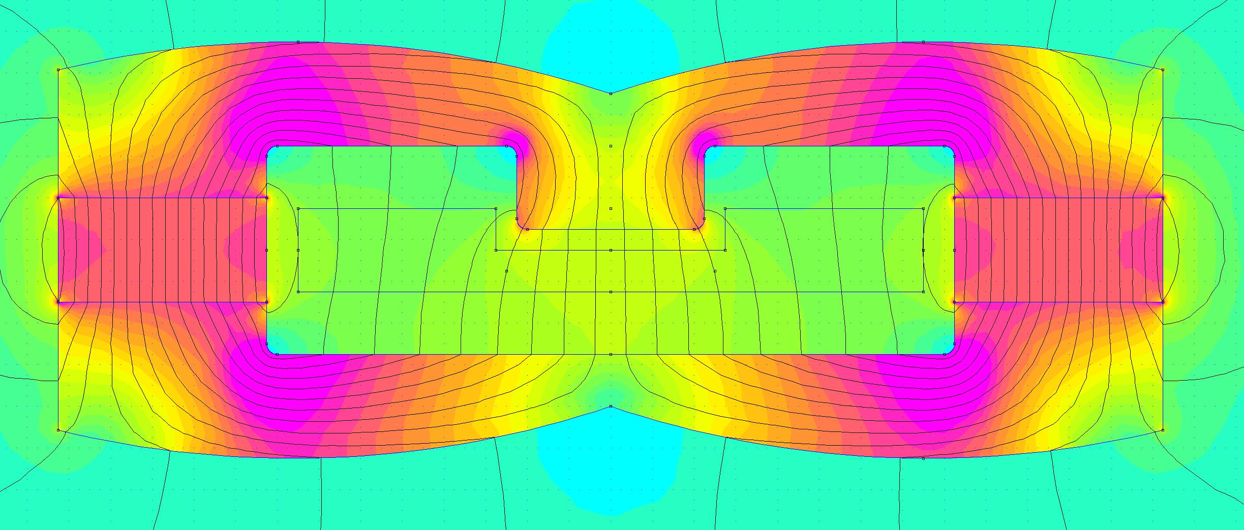
Simulated:
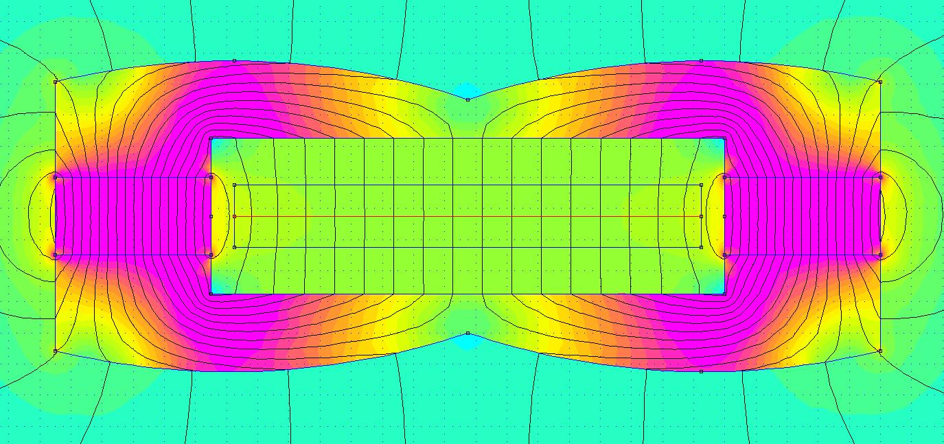
Magnetic flux density in the gap:
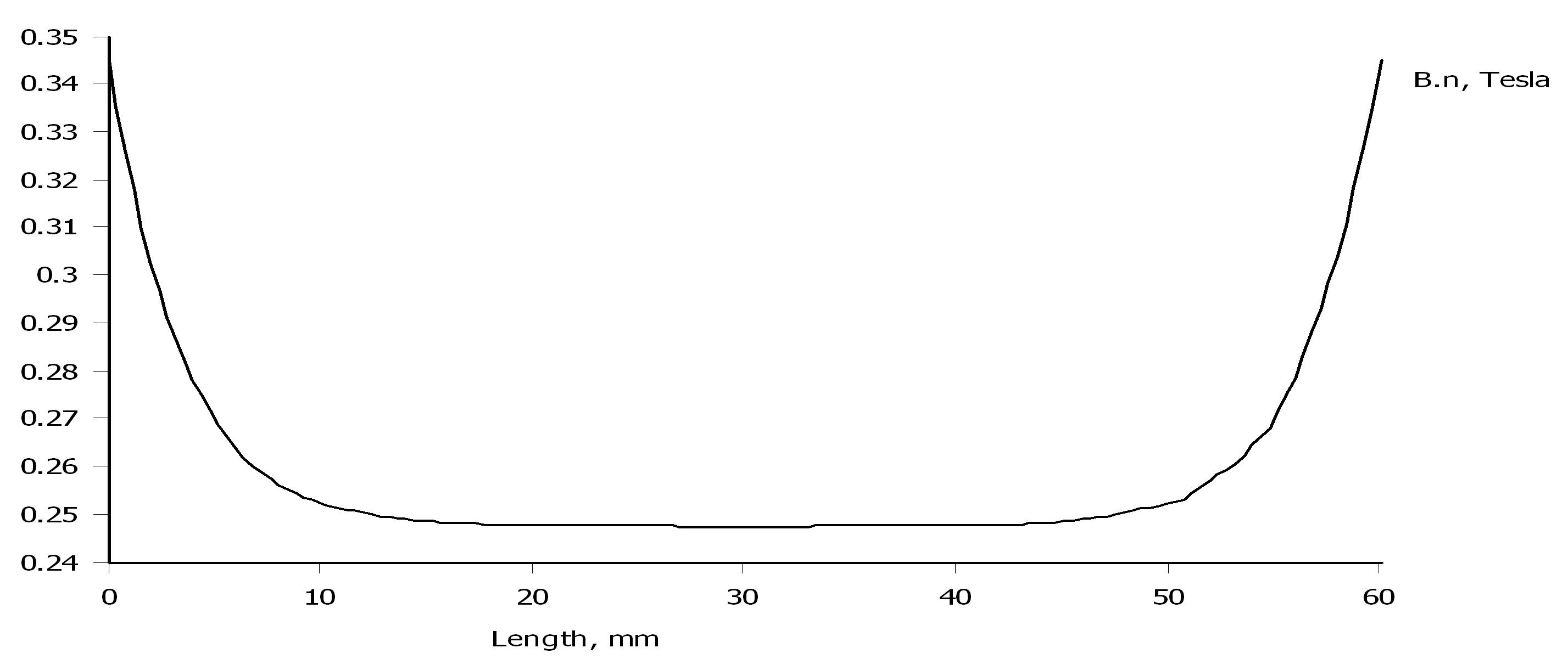
The magnetic flux density is about half of what SLAM! has, but as SALS?A! is three times as long I reckon that the sensitivety will be in the same range.
That is around 100 dB/1m/1W.
I'm a little bit concerned how a MTMMTMMTM, as three stacked SLAM! would be, would be as a true line source.
Even if the M and T are playing in the range in the lower frequencies; T takes over above 10 kHz, it might be ok in the far field.
Then I was thinking of the possibility to make a broadband membrane using various pleat depths across the gap. As HEDD AMT headphone.
That gives also the possibility to use the higher magnetic flux densities in the ends of the gap, that is between 0 and 10 and betwen 50 and 60 mm.
SALS?A! stands for Solhaga's AMT Line Source? Absolutely! and is a 220 cm long line source made of stacked broadband AMTs.
To just stack three SLAM! in a MTMMTMMTM configuration would be very costly as there's two magnets per centimeter and each magnet is €5.
So a weaker motor with one magnets standing instead of SLAM!s double laying magnets, would yield half a magnet per centimeter.
That is, only €500 worth of magnets for a full line source sized speaker.
Here's a first draft of the motor:
Simulated:
Magnetic flux density in the gap:
The magnetic flux density is about half of what SLAM! has, but as SALS?A! is three times as long I reckon that the sensitivety will be in the same range.
That is around 100 dB/1m/1W.
I'm a little bit concerned how a MTMMTMMTM, as three stacked SLAM! would be, would be as a true line source.
Even if the M and T are playing in the range in the lower frequencies; T takes over above 10 kHz, it might be ok in the far field.
Then I was thinking of the possibility to make a broadband membrane using various pleat depths across the gap. As HEDD AMT headphone.
That gives also the possibility to use the higher magnetic flux densities in the ends of the gap, that is between 0 and 10 and betwen 50 and 60 mm.
Last edited:
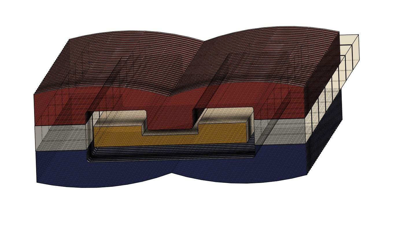
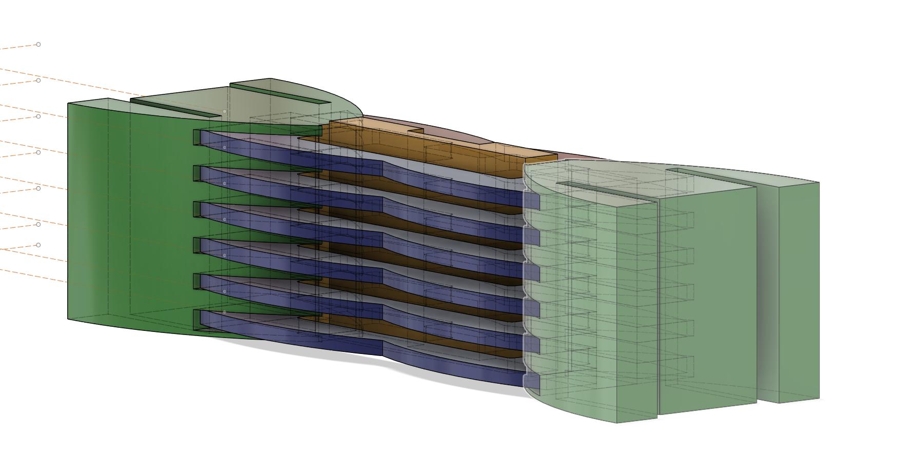
If the tweeter is in the middle of the membrane, the back pole piece must be closer there to reduce the reflections that can interfere with the forward sound wave.
The forward pole pieces will be glued to the structure, but the back pole pieces, only adhering to the magnet, can be replaced.
The pole pieces will probably in 2 mm steel.
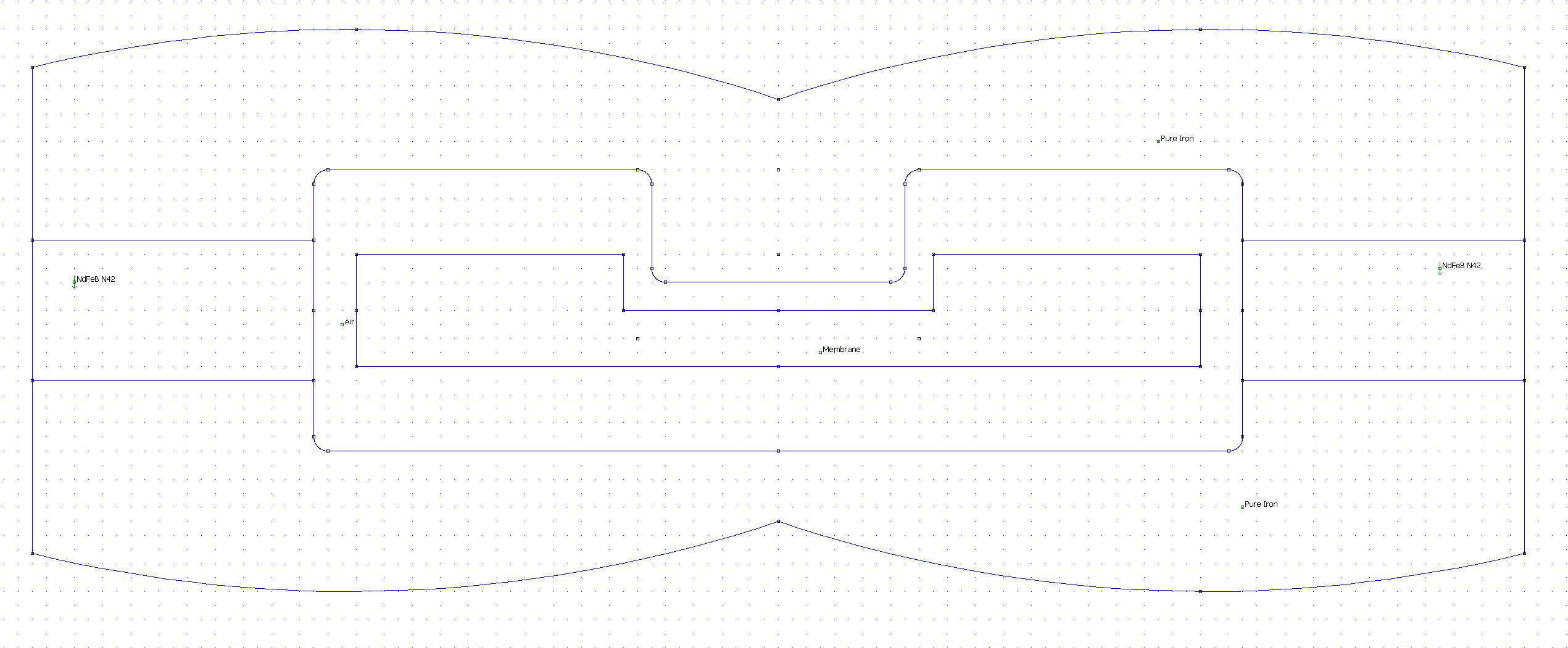
So here the membrane is a MTM in the horizontal plane, that is from the left to the right.
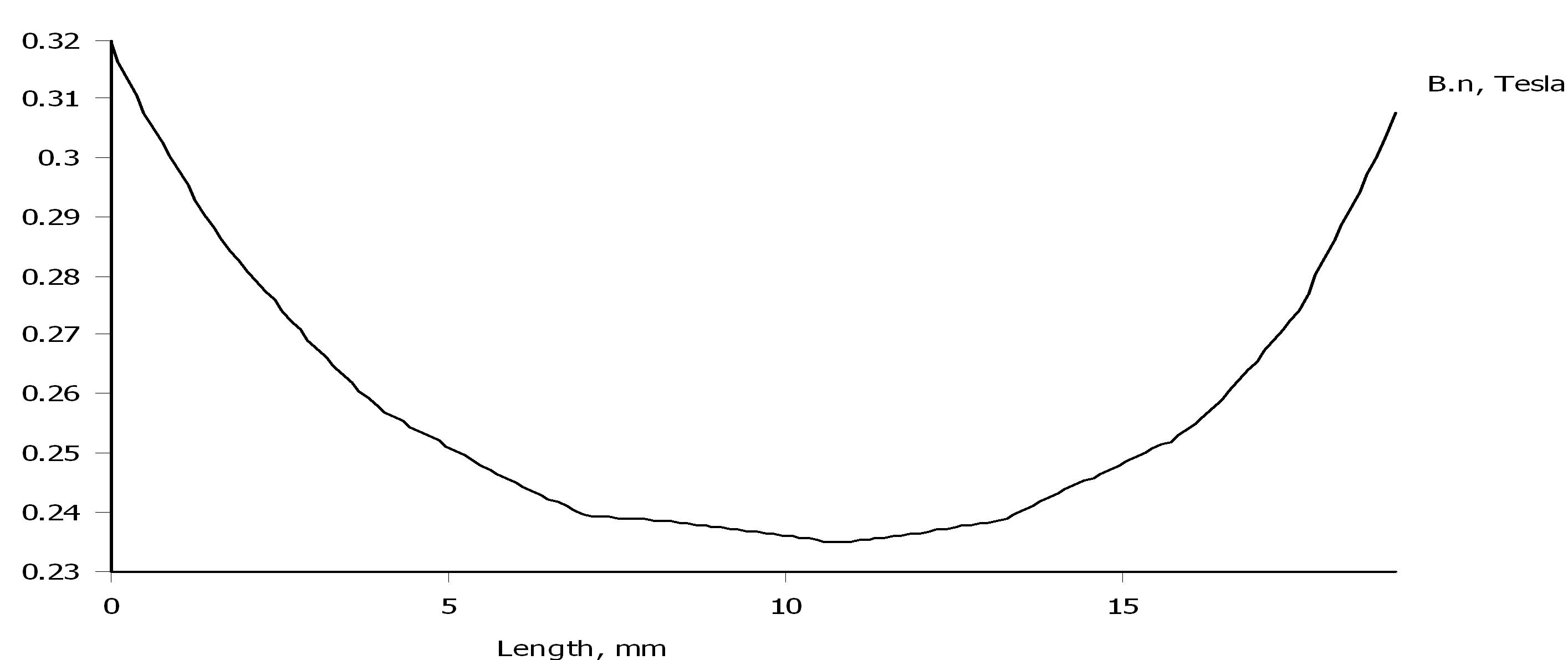
But the magnetic flux density will not be as linear as it the post above:
So some work remains no optimize the pole pieces.
Tweeter plotted:
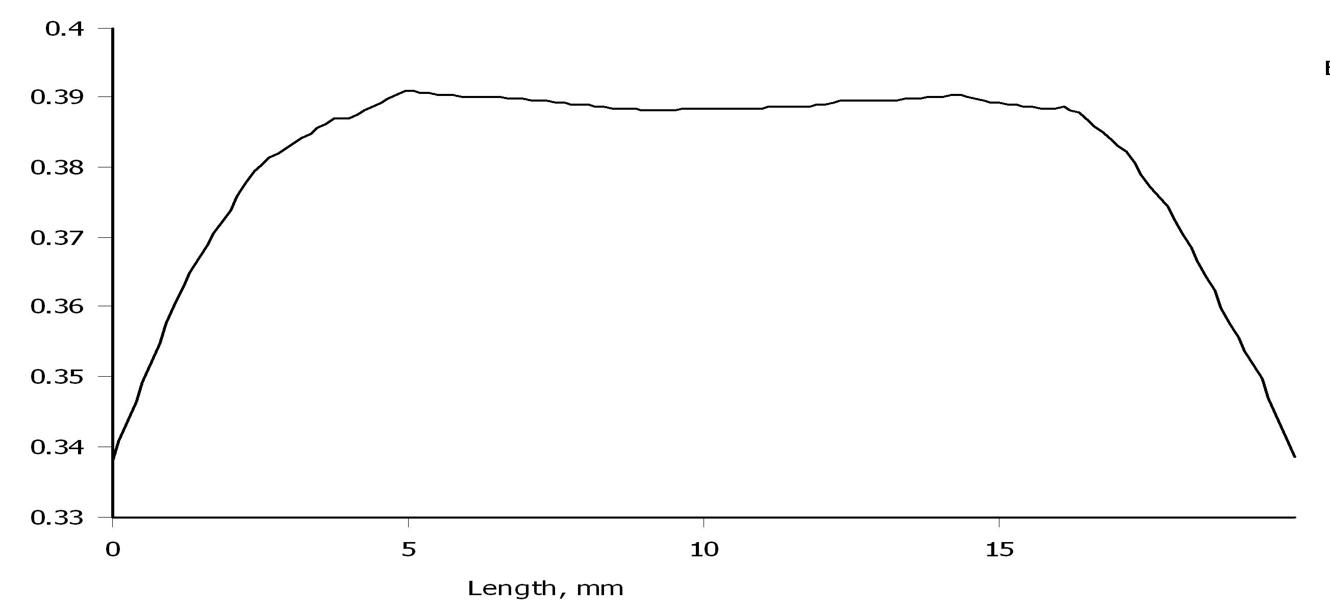
Middles plotted:
The forward pole pieces will be glued to the structure, but the back pole pieces, only adhering to the magnet, can be replaced.
The pole pieces will probably in 2 mm steel.
So here the membrane is a MTM in the horizontal plane, that is from the left to the right.
But the magnetic flux density will not be as linear as it the post above:
So some work remains no optimize the pole pieces.
Tweeter plotted:
Middles plotted:
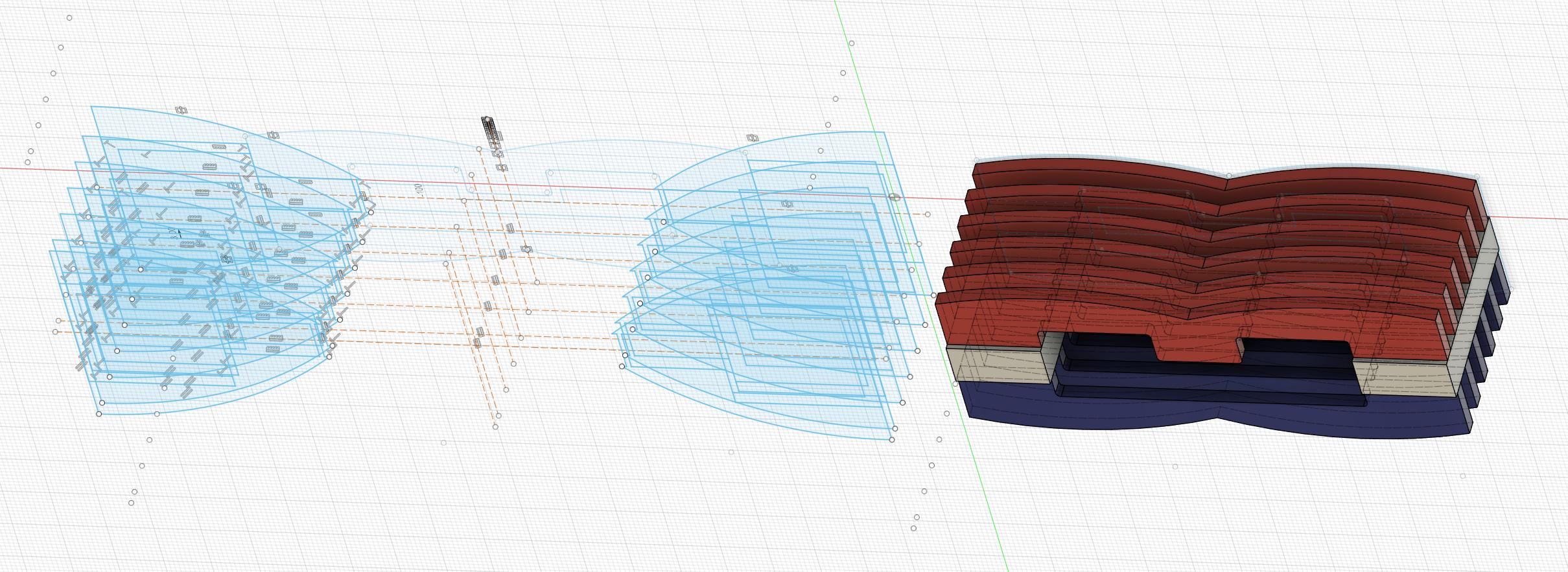
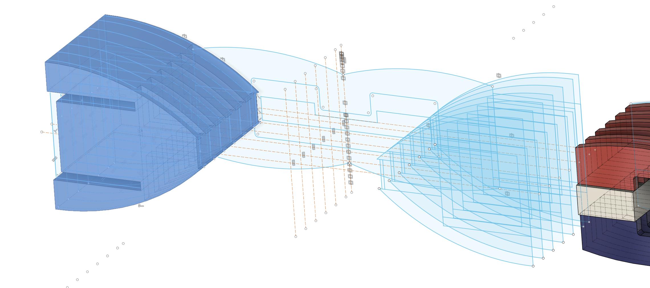
The pole pieces will be made of 3 mm steel, but the distance between the pole pieces will be 4 mm.
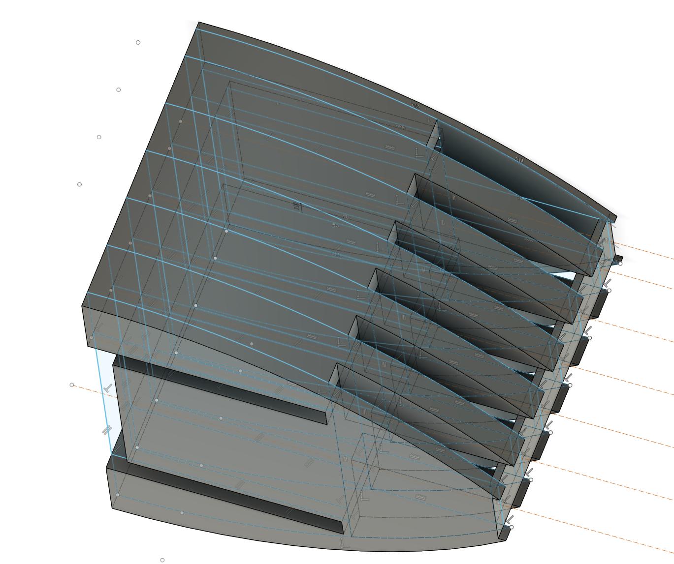
Here's some visualizations:
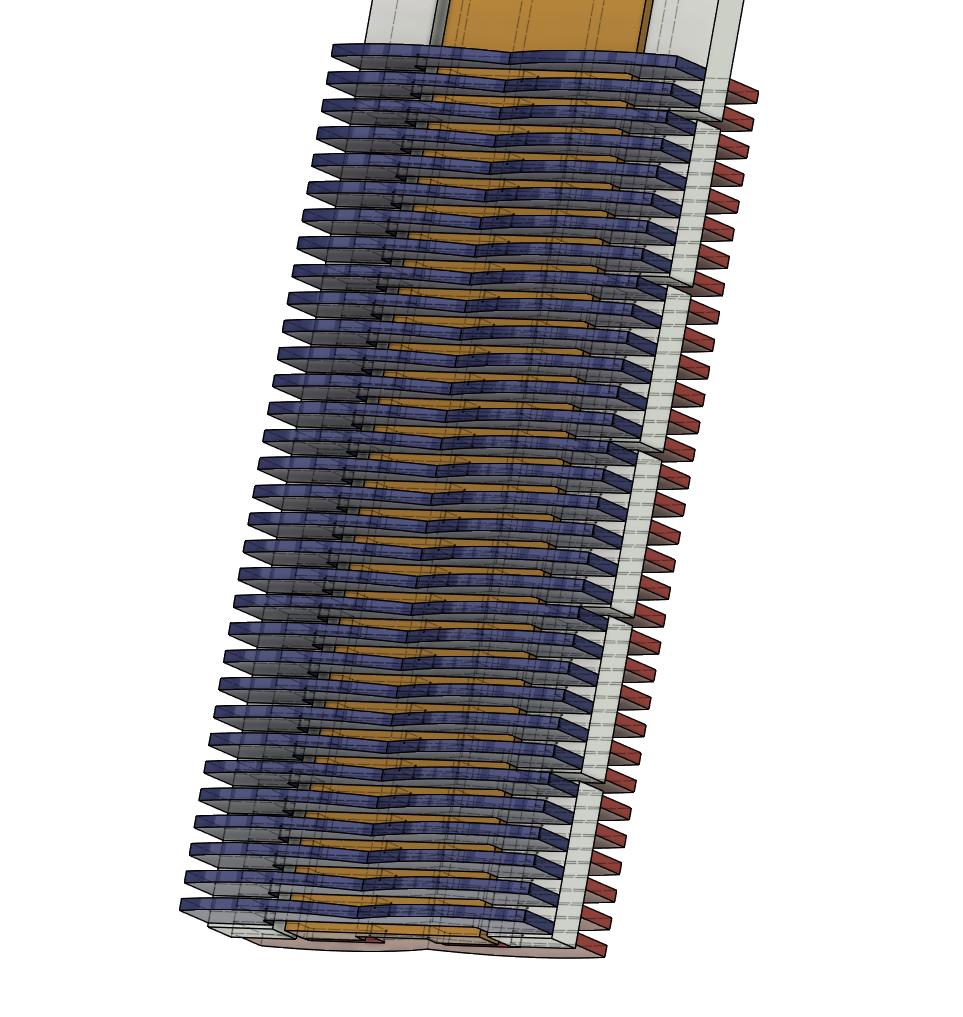
The magnets are not mounted back to back, there's a 2 mm gap between each magnet.
I will make a mounting cassette around every magnet pair so the 1 mm material on each side of the magnet is needed.
It'll be easier to slide down the mounting cassettes on the U-profiles that will make the sides.
Here's some visualizations:
The magnets are not mounted back to back, there's a 2 mm gap between each magnet.
I will make a mounting cassette around every magnet pair so the 1 mm material on each side of the magnet is needed.
It'll be easier to slide down the mounting cassettes on the U-profiles that will make the sides.
A full deck of sections as the one to the right is then needed for each loud speaker (around 220 cm):
The magnets and pole pieces are mounted with the cassett around each magnet and pole piece end. In the picture above an embryo is shown to the left.
The finished section is then pushed on to 30x30x30x3 mm aluminium U-profiles at the end of the cassettes.
This is how the first draft looks like:
I will pause near the end when printing the cassette in order to push in the magnet.
The contiuned print will seal the cassette.
I don't need to think of the polarity of the magnet as the cassettes are symmetrical.
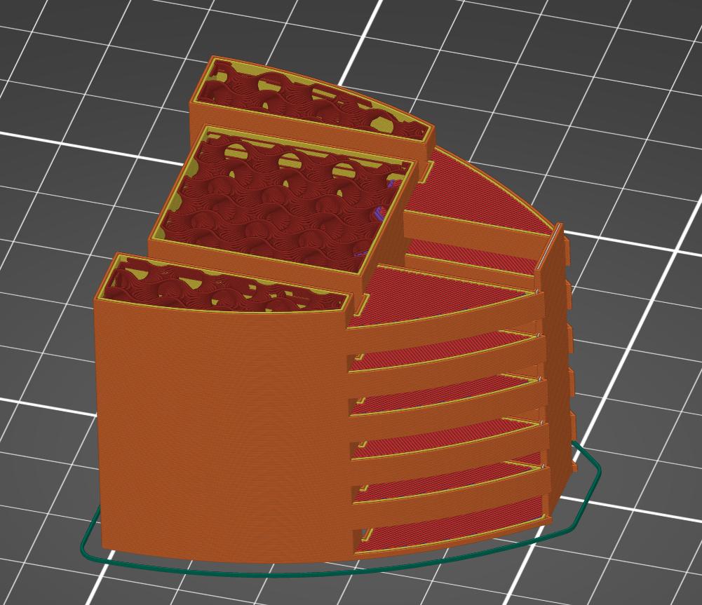
As I want smooth surfaces for the sound waves, I must orient the print so that support is needed for the empty spaces for the pole pieces:
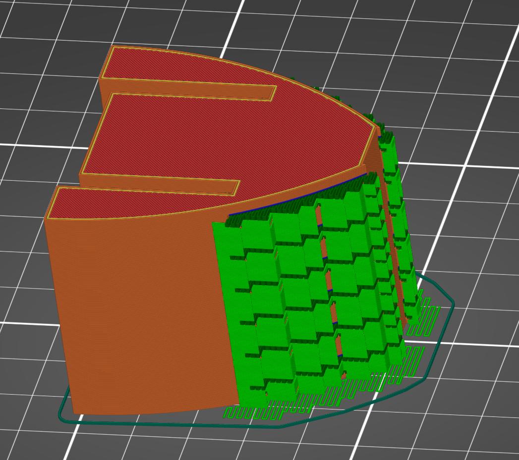
The supports are easily cut out.
One half of a section will take almost four hours to complete but I hope that I can manage to print two at a time.
Provided the that the magnets doesn't jump of course.
With two batches a day it will take 52 days to complete all 104 sections.
But already after five days I will have enough to start experimenting with the membrane, and that will take time.
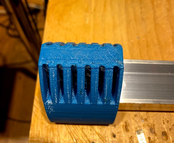
This is how the cassette and magnets and pole pieces look like:
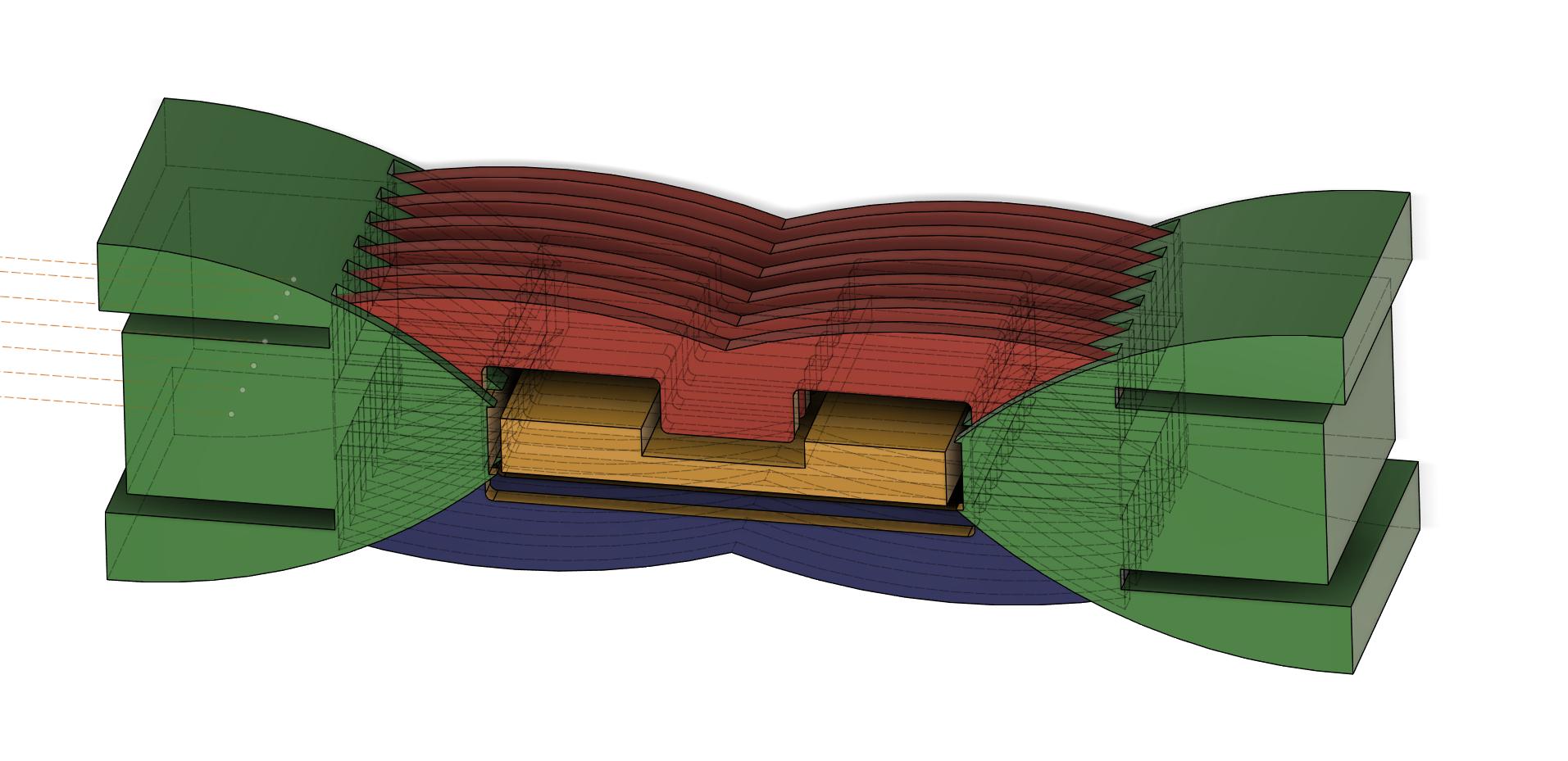
Front view:
Here you can perhaps get a better view.
The sections are the fastened using screws though the width of the U-profile.
The magnets and pole pieces are mounted with the cassett around each magnet and pole piece end. In the picture above an embryo is shown to the left.
The finished section is then pushed on to 30x30x30x3 mm aluminium U-profiles at the end of the cassettes.
This is how the first draft looks like:
I will pause near the end when printing the cassette in order to push in the magnet.
The contiuned print will seal the cassette.
I don't need to think of the polarity of the magnet as the cassettes are symmetrical.
As I want smooth surfaces for the sound waves, I must orient the print so that support is needed for the empty spaces for the pole pieces:
The supports are easily cut out.
One half of a section will take almost four hours to complete but I hope that I can manage to print two at a time.
Provided the that the magnets doesn't jump of course.
With two batches a day it will take 52 days to complete all 104 sections.
But already after five days I will have enough to start experimenting with the membrane, and that will take time.
This is how the cassette and magnets and pole pieces look like:
Front view:
Here you can perhaps get a better view.
The sections are the fastened using screws though the width of the U-profile.
The design principle for the membrane:
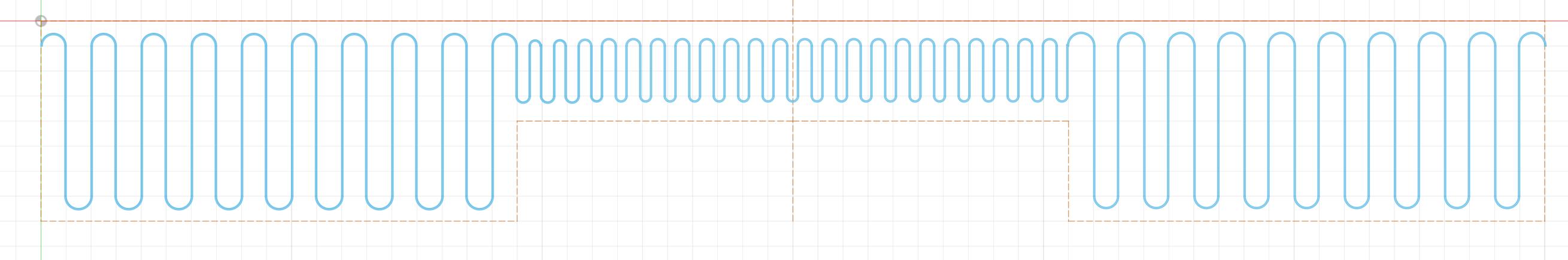
The tweeter part in the middle could be less I guess.
The length of each membrane is 320 mm:
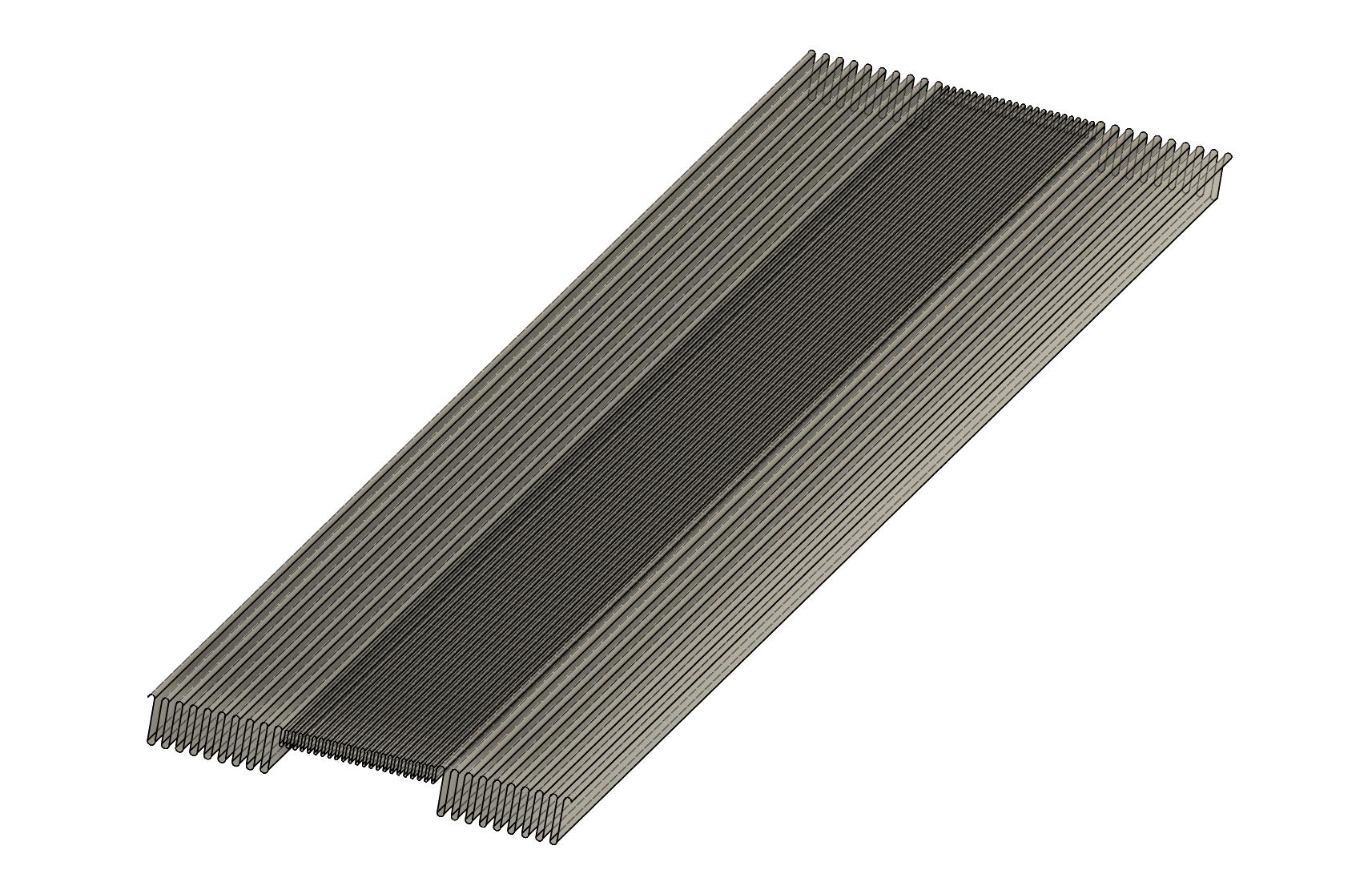
It might not be possible with that length; the tweeter part will be very difficult to fold.
The tweeter part in the middle could be less I guess.
The length of each membrane is 320 mm:
It might not be possible with that length; the tweeter part will be very difficult to fold.
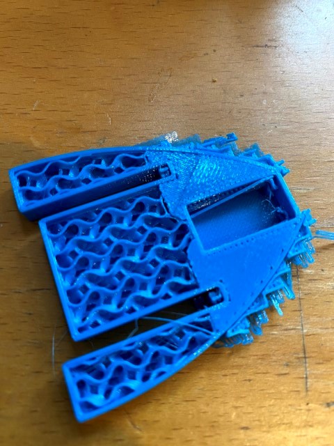
First print of a cassette.
The prints will consume over eight PETG filament rolls, so I will start with the ones that I have at home already.
So the finished speaker will be multi-colored, but I reckon that it can spray paint it later.
Or perhaps the multi-colored speaker will be a pleasant design.
First color is heaven blue.
Half an hour into the print, I discover that the support is also where the magnet are supposed to be pushed in and I can't trim that on the bed.
And there's unwanted support on the wave guide.
The wall between the magnet and the membran should be a multiple of the nozzle width 0.4 mm.
Now the wall is 1.0 mm so I'll make it 1.2 mm.
For increased strength, I'll increase the number of perimeter shells from two to four.
So there will be some changes on both CAD and CAM.
But that was expected.
Last edited:
Second iteration went a little better; I flipped the cassette.
The print out is paused when it's time to push in the magnet:
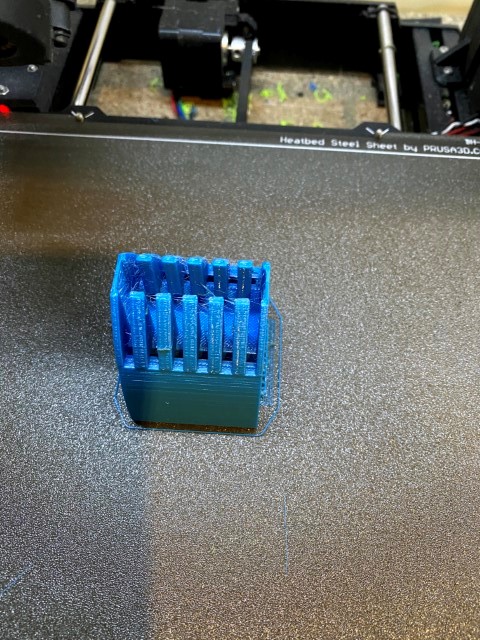
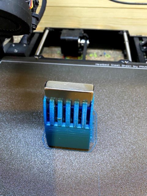
The printout then finishes and seals the gap for the magnet:
After some clean up:
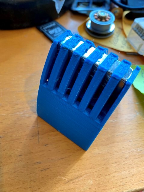
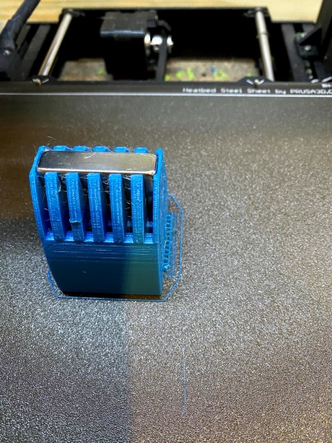
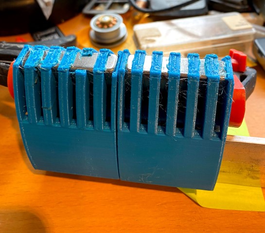
The mounting principle works; I can put two cassettes together with any magnet jumping out:
Alas is the dimensions for the cut-out for the U-profile a little optimistic and the top layer, that is the one that seals the magnets, hasn't that great finish.
So there will be another iteration, this time the U-profile will be 20x30x20 mm.
The print out is paused when it's time to push in the magnet:
The printout then finishes and seals the gap for the magnet:
After some clean up:
The mounting principle works; I can put two cassettes together with any magnet jumping out:
Alas is the dimensions for the cut-out for the U-profile a little optimistic and the top layer, that is the one that seals the magnets, hasn't that great finish.
So there will be another iteration, this time the U-profile will be 20x30x20 mm.
Yes, it is a long story in many aspects.
I still haven't figured out how to make the PETG filament attach to the magnet when completing the print.
Perhaps tape?
I still haven't figured out how to make the PETG filament attach to the magnet when completing the print.
Perhaps tape?
You could try spray painting the magnets also.
Perhaps thicker tape or multiple layers work as thermal insulation, preventing fast cool down of the plastic material.
Or preheating the magnets up to 60...70C...
Perhaps thicker tape or multiple layers work as thermal insulation, preventing fast cool down of the plastic material.
Or preheating the magnets up to 60...70C...
Max. operating temp is specified for every magnet type.
N: 80C (but N52 is only 65C)
M: 100C
Hi: 120C
N: 80C (but N52 is only 65C)
M: 100C
Hi: 120C
Thanks for your suggestions.
It is not about the heating of the plastic when pausing.
The previous layer is always cold when printing; it is the heat of the current layer that re-melts the previous layer and the current layer together.
Pausing is the normal procedure when for example changing color or type of filament, inserting bearings or magnets.
The issue here is to make the final layers stick to the glossy magnet.
Some kind of paint could do or perhaps tape.
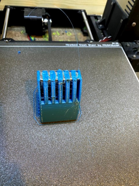
I tried with a glue stick:
I also need to counter sink the magnet half a millimeter or so; there's a gap between the top layers and the rest.
I must get this right, it would not be good if I have to change half way.
It is not about the heating of the plastic when pausing.
The previous layer is always cold when printing; it is the heat of the current layer that re-melts the previous layer and the current layer together.
Pausing is the normal procedure when for example changing color or type of filament, inserting bearings or magnets.
The issue here is to make the final layers stick to the glossy magnet.
Some kind of paint could do or perhaps tape.
I tried with a glue stick:
I also need to counter sink the magnet half a millimeter or so; there's a gap between the top layers and the rest.
I must get this right, it would not be good if I have to change half way.
I was thinking of folding the tweeter part of the membrane first, followed by one outer mid range section.
The folding jig must then be detachable so it can be turned around to fold the other mid range section.
An externally hosted image should be here but it was not working when we last tested it.
The folding jig must then be detachable so it can be turned around to fold the other mid range section.
Last edited:
I will cut out the laths of the folding tool with my plasma cutter.
That way I obtain the different thicknesses and depths of the pockets.
That way I obtain the different thicknesses and depths of the pockets.
Blue painter's tape on the magnet did the trick.
Eight down, 200 to go:
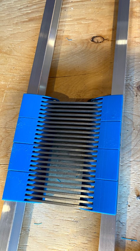
Here they are mounted with default pole pieces.
With perfect timing I can make six a day, but most probably it will be only four.
So it will be 35 to 53 days until they are ready.
Eight down, 200 to go:
Here they are mounted with default pole pieces.
With perfect timing I can make six a day, but most probably it will be only four.
So it will be 35 to 53 days until they are ready.
It kinda looks like a Goliath-version of the classic ESS Heil.
Very impressive work!
Very impressive work!
Last edited:
very nice as usual !!!!! the tweeter part is driven separately ? since if it is just like this headphones, you might run into troubles nearing the resonance of the tweeter part ?
some insane build by the way 🙂
some insane build by the way 🙂
Thank you.very nice as usual !!!!! the tweeter part is driven separately ?
Yes, the tweeter has its own driver and DAC channel.
I'll be using Convolution for cut-off and EQ.
Yes, that will be a challenge.since if it is just like this headphones, you might run into troubles nearing the resonance of the tweeter part ?
It will probably be seven membranes per speaker with supports at their ends.
But I might need to have support in between as well to mitigate resonances as you mention.
The back pole pieces will also be subject to several incarnations to minimize the reflections that is caused by the back sound wave.
some insane build by the way 🙂
70 cm finished, 370 cm to go.
Third roll of filament.
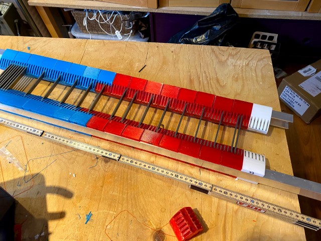
Is it the French or Dutch flag?
- Home
- Loudspeakers
- Planars & Exotics
- SALS?A! - a very long story