$45K amp ???
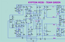
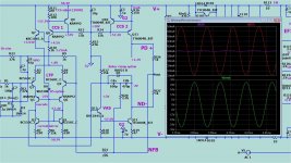
1990's luxman IPS .... (below)
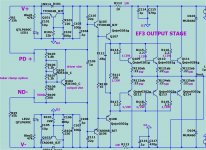
Our EF3 likes it !!
By simulating this , I'm in awe of the Japanese.
Lead , lag , and nested FB ... What games you can play.
This was built in the slewmaster (clusteryouknowwhat).
At 53 , I did not appreciate the splender of his level of forethought.
At 57 , I can actually visualize it. Kypton bode can be "bent" any where I want
it. Boosted at 20K , I can get TMC performance without tmc. Phase margin
is "bendable" with 3 nested players. LTP feeding LTP also helps.
The original LT slewmaster "kypton" had flaws (but worked). Amazing!!
(below)
This IPS uses 11.5mA per rail @ 4.1mA VAS. Just 11 semi's (including the
regulators). Just a HV op-amp...
PS - I drank S. American vino in the development of this cool design.
OS
1990's luxman IPS .... (below)
Our EF3 likes it !!
By simulating this , I'm in awe of the Japanese.
Lead , lag , and nested FB ... What games you can play.
This was built in the slewmaster (clusteryouknowwhat).
At 53 , I did not appreciate the splender of his level of forethought.
At 57 , I can actually visualize it. Kypton bode can be "bent" any where I want
it. Boosted at 20K , I can get TMC performance without tmc. Phase margin
is "bendable" with 3 nested players. LTP feeding LTP also helps.
The original LT slewmaster "kypton" had flaws (but worked). Amazing!!
(below)
This IPS uses 11.5mA per rail @ 4.1mA VAS. Just 11 semi's (including the
regulators). Just a HV op-amp...
PS - I drank S. American vino in the development of this cool design.
OS
Attachments
I wanted to ask , I have the options of pulling G2/Glift (Canada traces)
from PS ground , speaker ground , or the G1 via's.
Are you sure speaker ground is best ?? The return of the speaker would be
in phase with output/ NFB at AF. Self hints at G1 for any aux. grounds. 😕
OS
G2 is less critical because any noise on it is attenuated by PSRR. But since G2 feeds the CMs it will just be the amp's base PSRR. So G2 could be moved to G1.
In this case the impedance from speaker ground to G1 ends up becoming part of the supply impedance seen by the amp, therefore it is reduced by PSRR just like ripple. The voltage does stimulate the input ground loop, but with a groundlift resistor the effect is minimal. It would be desirable to bring the feedback ground and G1 closer but this requires opening up the feedback loop right in the middle of the PSU current loop which cancels any potential gains.
On the other hand with FBG and G2 both at the speaker ground, you can think of it like the frontend is "floating" on the voltage of the negative speaker terminal. So the voltage does not affect response because the signal and reference are both disturbed by the same signal. The only place where a reference error might occur is with the source, which is referenced to safety earth, but depending on where the amp connects to safety earth, other sources of ground noise may be much worse than what is on speaker ground.
Here is a suggestion that may address all concerns: Bring G1 outside the PSU current loop. This means the ground inductance will all be on the PSU side so the amp will just see it as a PSU impedance. With G1 outside the PSU loop we no longer have to run sensitive traces into the PSU loop. BUT, we still have to keep from opening up the feedback traces. We are basically making a Kelvin connection at the speaker output terminals because anything less creates a significant pickup loop for the nearby PSU traces.
Last edited:
Yes , KT. The Zobel can be a very big HV unit.
It needs to have high current rating, IE pulse rated. A metallized HV cap may burn off the metallization at high current swing like you would see if your drivers decided to blare 96KHz into the amp, or if there was oscillation.
Kelvin connection....
That gets a lot of hits !
So , keep the FB loop to speaker GND. G2 --- G1 Via. (below).
It just keeps looking better !🙂
My IPS's fit , 12 pin DIP , 4 pin header ... errors gone. Many macro's were in
multiple groups - all components now are complete macro's. Some component
housekeeping might be needed.
I did keep many of Stuarts better ideas , screen and larger components.
OS
Attachments
1990's luxman IPS .... (below)
Our EF3 likes it !!
By simulating this , I'm in awe of the Japanese.
Lead , lag , and nested FB ... What games you can play.
This was built in the slewmaster (clusteryouknowwhat).
At 53 , I did not appreciate the splender of his level of forethought.
At 57 , I can actually visualize it. Kypton bode can be "bent" any where I want
it. Boosted at 20K , I can get TMC performance without tmc. Phase margin
is "bendable" with 3 nested players. LTP feeding LTP also helps.
The original LT slewmaster "kypton" had flaws (but worked). Amazing!!
(below)
This IPS uses 11.5mA per rail @ 4.1mA VAS. Just 11 semi's (including the
regulators). Just a HV op-amp...
PS - I drank S. American vino in the development of this cool design.
OS
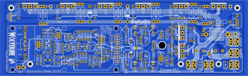
Is the Wolverine finished already? I must have missed it!
Wolverine is never "finished".
# 1 - technical excellence.
The second most important aspect of this board is ......
Modular. (below)
Mine will be this ! 🙂🙂
Have patience ... a fine wine does not happen overnight.
PS - see the tiny alignment issue. Along with this IPS/MB alignment , UMS alignment also must have utter perfection. The spooky shown is accurate to
.1mm ... the main EF3 (MB) must have a slight offset.
Edit - had to slightly redesign Spook per KT's grounding rules (G2/GLift).
OS
Attachments
Last edited:
Why not full modular.
From a build guide and mechanical standpoint , this might be the better way.
From the store standpoint , a slightly more expensive 2 PCB set.
From the builders standpoint , just a look at the hairpulling going on in this
thread would show the superior project they could choose.
The Wolverine can just be the showcase default IPS .... I just ported it
to a blank IPS.
End builder would just get the brochure(s) that would be (EF3-Wolverine) or
(EF3 - Spooky).... or whatever else.
What the heck ... UMS also supports 12 device dual row layouts.
Why not even make a UMS "ARCwelder" plus.
OS
This is what the store set will be ....
I going for it. I won't back down.
Along with branded build guides which will include -
-History
-circuit operation
-general building
-Adjustment and testing
The EF3 will have -
-History
-circuit operation
-general building
-Adjustment and testing (in isolation).
Plus .....
-thermal
-Safety
-How to run the OPS in isolation.
-interaction with IPS's and standards.
I feel this would counter increased cost. Safety is priceless.
PS - more might read the "Slewmaster" thread (just 2M views now).
OS
Attachments
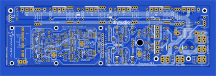
Hi OS. Maybe you could move the input connection on the spooky a little more to the left.
As it sits i belive the the mounting hole next to it comes in conflict with the euroblock and maybe the input ground trace.
Or remove that mounting hole all together.
As it sits i belive the the mounting hole next to it comes in conflict with the euroblock and maybe the input ground trace.
Or remove that mounting hole all together.
The IPS sits on top of the mounting screw. You won't see it with the IPS
mounted on it's standoffs.
I knew someone would notice that - as an error. But it's not. 😀
The male header on the main board is 3mm thick with 6mm pins on top
The female is 9mm - we'll be 12-13mm off the board.
They make a shorter female where you would be 9mm -1cm high.
OS
mounted on it's standoffs.
I knew someone would notice that - as an error. But it's not. 😀
The male header on the main board is 3mm thick with 6mm pins on top
The female is 9mm - we'll be 12-13mm off the board.
They make a shorter female where you would be 9mm -1cm high.
OS
So it's not ment to use the monting hole next to the input on the IPS board?
I was thinking, standoff, mainbord, standoff, IPS board. But one don't need 7 mounting points for the IPS.
I was thinking, standoff, mainbord, standoff, IPS board. But one don't need 7 mounting points for the IPS.
You do use it. When you mount JUST the power board to the heatsink.
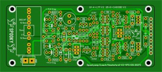
And fully bias it in isolation. (below) Just 15K PD+/V+ ... ND-/V-.
all prebiased for 70-100mA per device.
THEN you could even use 12mm plastic snap in spacers on either 4 or
6 of the holes.
Any IPS can be run in isolation , power it up - 1K each to PD+/ND- ... center
of these to NFB. You could even adjust VAS I , measure 8V across PD+/ND-.
That's 4 mA.
Then when you plug in the IPS , it will definitely work ....
OS
Attachments
Hi OS,
You have made a number of important changes. Many thanks. However some of us have lost track.
Are you able to post the latest schematic (Wolverine) sprint file and template for the IPS, so we can start checking creapage, component spacing etc?
You have made a number of important changes. Many thanks. However some of us have lost track.
Are you able to post the latest schematic (Wolverine) sprint file and template for the IPS, so we can start checking creapage, component spacing etc?
Nothing radical ...
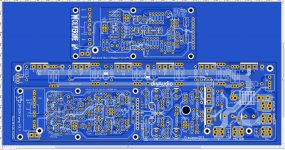
Main board , Spook , and Wolverine are storebound.
You can batch check any IPS for creep in 30 seconds.
Stuart showed that a little can go a long way for a pretty board.
JK's original Spooky was the coolest audio board I ever populated.
(below) I'm doing the Spook and Wolverine now (complete with component
extended info).
Going full modular is the way . You can compartmentalize IPS/OPS builds.
I already use divided numbers , IPS's are R1,2,3 OPS's are 101,102 ...
OPS and Wolverine have had 4 eyes on them .... just do component housekeeping.
Spook might need some eyes. 😀
PS - I'll post the 3 storebounds ...
OS
Attachments
Last edited:
#795 C7 non polar electrolytic can be rotated 90deg clkwise.
Dont see many non polar electrolytics here.
Dont see many non polar electrolytics here.
Main board , Spook , and Wolverine are storebound.
You can batch check any IPS for creep in 30 seconds.
Stuart showed that a little can go a long way for a pretty board.
JK's original Spooky was the coolest audio board I ever populated.
(below) I'm doing the Spook and Wolverine now (complete with component
extended info).
Going full modular is the way . You can compartmentalize IPS/OPS builds.
I already use divided numbers , IPS's are R1,2,3 OPS's are 101,102 ...
OPS and Wolverine have had 4 eyes on them .... just do component housekeeping.
Spook might need some eyes. 😀
PS - I'll post the 3 storebounds ...
OS
Thanks to you and your colleagues for the work!
It will be nice to have all the info for the build and testing in the store.
Is there a CFA input board option?
I am definitely building this!
why don't you make the amp board in the same format as in my screenshot?
The location of the board's power polygons does not seem optimal to me, they are too elongated and thin, like antennas.
What disadvantages do you see in my version of printed circuit boards
The location of the board's power polygons does not seem optimal to me, they are too elongated and thin, like antennas.
What disadvantages do you see in my version of printed circuit boards
Attachments

One goal is the have the boards compatible with the UMS heatsinks from the store. I believe the design you have shared would make that challenging. Also there is a goal to have the power devices in one row on the top side of the board for better thermal performance (I could be mistaken here).
- Home
- Amplifiers
- Solid State
- DIYA store "Wolverine" (Son of Badger) .... suggestions ??