If you are measuring 250Vac before the rectifier under load, you should be getting a lot more than 315Vdc after it.Yup, thanks for help and all the extra information too 😀
So i took the isolation transformer and my analog scope, 10x attenuation on probe/10V per div. Measured from the leads of power trafos 250VAC secondary, while connected to bridge.
First the reading on my multimeter.
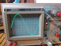
Second the waveform right after power up. (cathode still heating)
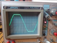
Third after the current starts to flow.
First the reading on my multimeter.
Second the waveform right after power up. (cathode still heating)
Third after the current starts to flow.
Attachments

So looking at the circuit you posted in post #14 you should be seeing the value of the flat topped part of that AC voltage as appearing across C5. There will be ripple but the bridge output has to rise to that level (less diode losses of course which will be under 2 volts).
(A 1 to 1 isolation transformer will probably have significantly higher output at low loading)
(A 1 to 1 isolation transformer will probably have significantly higher output at low loading)
Member
Joined 2009
Paid Member
If there is some question about the transformer....the manufacturers are ‘supposed’ to give the secondary voltage under nominal load. If you load the transformer secondary with a power resistor with no rectifier then you should see full rated voltage.
From little load (only filaments) to full load, peak voltage (which is the value to which capacitors will charge) loss, is 20%Second the waveform right after power up. (cathode still heating)
Third after the current starts to flow.
A SIGNIFICANT loss.
Yes, I enlarged the image and counted divisions.
If you measure from NO load (not even filaments connected) to FULL load, difference will be even larger.
BESIDES: a regular multimeter will NOT measure the second waveform and the third one the same way, so we can not consider "250V" displayed on both cases as meaning the same, even if "numbers" match.
To be more precise: whether I measure both waveforms with a true RMS meter, or a cheaper "Average factored to RMS", if both display "250V", capacitor DC voltages will be different, lower in the flat topped third one, because it will have lower peak value.
Like 6A3Summer said , an old fashioned VTVM will give better results, because they measure peak voltages.
An old fashioned analog/needle type meter, will show average-factored-to-RMS voltges, because of moving coil and needle mechanical integration.
A Scope will show the full picture. (duh! 😛 )
A Shower will clean you well.
You waveform has an extraordinary flat top, that's one heck of a conduction angle! Seems to me something is drawing excessive load current somewhere.
- Home
- Amplifiers
- Tubes / Valves
- Power tube supply voltage drop