Thanks, Nelson. I went through and measured everything I could get to.
Results attached.
Next I’ll compare to the left channel.
Then disassembly to get at the TO3 pins... I think I can take the bottom pate off after unscrewing the filter board. Then I could stand the amp in the faceplate (with scratch protection)...
Do you have 13,7 volts on the inputs?
@ von Ah
All solder joints of big C1 output stage cap are OK ?
I’ll find that out soon. Will be taking the bottom plate off momentarily.
Power resistors all measure 1.2V across them for both channels.
Do you have 13,7 volts on the inputs?
On both sides of R1, yes. That baffled me, too. But 5mv at input and input GND.
Same on Left channel.
Second question to everyone in Europe. Did you get your components yet?
Mine are stuck in Germany since last weekend.
No but next week very possible, components and chssis finnaly in France.
Monday or Tuesday I hope 🙂
On both sides of R1, yes. That baffled me, too. But 5mv at input and input GND.
Same on Left channel.
recheck that
try shorting inputs via 1K resistor, it can be just floating mess
when you're here - check continuity of both primary and secondary of Edcor
In the last picture in building guide the power supply wires are twisted but not on previous images (only signal wires)?
Is there a recommendation to twist the DC-power wires (pairs) or not?
Is there a recommendation to twist the DC-power wires (pairs) or not?
... adding motor run caps to the power supply, separate for each channel.
Sometimes I just can't help myself.
Salieri touching up Mozart opera...
"Grazie Signore..." 🙄
Last edited:
The Mean Well SMPS switches at 220 kHz (citation).
What number do you get when you estimate the self resonant frequency of that motor run capacitor with those leads? I get approx 50 kHz.
That looks awfully dangerous to me and I recommend NOT doing it.
close to 1/4 wavelength too, it could not have been picked better.
On both sides of R1, yes. That baffled me, too. But 5mv at input and input GND.
Same on Left channel.
Maybe you have C1 shorted somehow? R1 should be at 0V on both sides.
Check input jack connections, both center pin to R1 and shell to circuit GND.
Hmm, maybe also check continuity of Edcor transformer secondary -D and +D connections to the output stage.
Also double-check your R5 connection. It should have the same DC voltage as R1 on it (0V). So if it's measuring 1.5mV while R1 is at 13.78V, something is amiss there.
I don’t think it has anything to do with 1/4 wave length of the wire. Electricity travels 11in per nano second. 1/4 wave of 50khz is about 1.4km long wire. I think adding a 0.22 ohm resistor in series might alleviate any concerns of an LC oscillator. The bigger problem to worry about is how much capacitance will make the Mean Well will go into hiccup mode at startup.
In the last picture in building guide the power supply wires are twisted but not on previous images (only signal wires)?
Is there a recommendation to twist the DC-power wires (pairs) or not?
I don’t think it really matters on the power wires. The smps is conveniently way outside of the amp, there is no noisey toroidal inside the amp. My power wires were not twisted and my speakers being so efficient usually magnify any potential noise... but this amp is creepy quiet!
In a more deliberate investigation I would have considered adding a 0.1 to 0.22 Ohm resistor in series with one of the capacitor leads to prevent oscillation.I don’t think it has anything to do with 1/4 wave length of the wire. Electricity travels 11in per nano second. 1/4 wave of 50khz is about 1.4km long wire. I think adding a 0.22 ohm resistor in series might alleviate any concerns of an LC oscillator. The bigger problem to worry about is how much capacitance will make the Mean Well will go into hiccup mode at startup.
The 1000 uF capacitors on the FE and OS boards do provide some local supply decoupling, at a reasonable amount that was likely determined to be compatible with the brick SMPS. The 70 uF oil-filled poly caps can help with the upper audio register, as long as they don’t cause oscillation.
Math says oscillation is prevented when the resonant circuit is critically damped (Zeta=1). To account for estimation inaccuracy, component tolerance, and human aversion to uncertainty & risk, perhaps it's best to aim for (let's just say) Zeta=2.
What series resistor gives Zeta=2?
Or, just as interestingly, what Zeta do you get when the series resistor is 0.22 ohms?
What series resistor gives Zeta=2?
Or, just as interestingly, what Zeta do you get when the series resistor is 0.22 ohms?

The bigger problem to worry about is how much capacitance will make the Mean Well will go into hiccup mode at startup.
Fortunately the Meanwell's start up into big capacitance is to pulse the
load for a while in the "hope of charging the capacitance". If the channels
to not initially draw much current, then this strategy tends to be successful.
These channels take a little while to develop bias, so it works out with the
1,000 uF. Probably you can go quite a bit higher.

Thanks for all the suggestions, gentlemen. I need to take a break and come back to the troubleshooting later with a fresh mind and back.
I don’t think it has anything to do with 1/4 wave length of the wire. Electricity travels 11in per nano second. 1/4 wave of 50khz is about 1.4km long wire. I think adding a 0.22 ohm resistor in series might alleviate any concerns of an LC oscillator. The bigger problem to worry about is how much capacitance will make the Mean Well will go into hiccup mode at startup.
About 50kHz is about 1/4 220KHz.
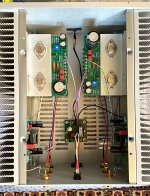
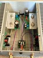
Finally done with the mechanical / electrical assembly of my Sony VFET amp. Next is checking the DC bias points, a small amount of burn-in to check for temperature, then listening!
Nice!
- Home
- Amplifiers
- Pass Labs
- DIY Sony VFET Builders thread