I'm at a loss with one of my F5 Turbo monoblocks. No matter what I try, I cannot fix a serious imbalance of the bias on the N-channel of one amp.
Let me start by saying that I have tried three sets of matched MOSFETs in the N-channel and replaced all the source resistors with 1% wirewound. But this has not stopped the voltage across the source resistor on the first MOSFET on the first n-channel board from being at least double the two MOSFETS on the second n-channel board. (The second MOSFET on the first board falls somewhere in between.)
If you assume the MOSFETS are properly matched and there is no major imbalance in the source resistors, what, if anything, could be causing this? I have tried changing the tightness of different mosfets and it makes only a small difference. The voltage is consistent across both boards (-40.6)
The p-channel is fairly closely matched across all four mosfets (within 20mv or so).
Any thoughts or creative ideas would be appreciated.
Like you said, MOSFETs changed along with source resistors, would have to be the diode. It is a v3 correct? Don't know how to test the diode in the circuit, it is supposed to reduce the source resistance.
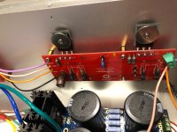
Post some pix.
How hot are you running the bias?
Have you changed out diodes?
Have you measured and written down current on each mosfet on both amps to compare how they’re performing?
Is there anything up with the front end board? What if you swapped front end boards between the monoblocs and see if the problem follows?
The bias is well below where the diodes should start conducting, especially because I haven’t cranked up the bias and the imbalance is there even when the amp is cold.
But I guess it is possible. If no other ideas come in, I can remove them and see if the imbalance remains.
But I guess it is possible. If no other ideas come in, I can remove them and see if the imbalance remains.
Post some pix.
How hot are you running the bias?
Have you changed out diodes?
Have you measured and written down current on each mosfet on both amps to compare how they’re performing?
Is there anything up with the front end board? What if you swapped front end boards between the monoblocs and see if the problem follows?
I will post some pics tonight.
The bias is low right now because I don't want to blow another set of mosfets and because the imbalance is so pronounced. The front mosfet is at .115V and the back two are only at 0.55V or thereabout.
I did change out the diodes when I rebuilt this entire section of the amp, including using new boards. But I may try removing them tonight to see if that fixes the problem.
Not sure how to test the current on each mosfet. I will write down all the individual voltages tonight, but let me know if there is another test.
I am loathe to touch the V3 that is functioning properly and don't want to remove the front end board from it unless there is a reason to do so. I haven't seen evidence that a problem with the front end board could be causing this issue, but if someone tells me I'm wrong, I'd be willing to try anything.
Measure voltages across the 1R resistors at each mosfet. You should only have to measure one, they're in parallel.
V = IR
I = V/R
I = voltage reading / 0.5 Ohms (NOTE: 2x 1 Ohm in parallel = 0R5)
Measure both amps marking down each mosfet's current to get a picture of what's going on. Ideally they're all showing pretty similar readings. If one is way off the rest you have to look at that one. Mosfet? Diode? resistors (47R5 or 1R)?
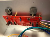
Some pictures are attached.
As you will see, the problem is definitely not the diodes, which I removed on that channel altogether today.
The measurements across the source resistors on the problematic channel are:
108.2mv
54.7mv
41.6mv
43.6mv
The measurements on the good channel are:
63.3mv
66.4mv
61.4mv
57.7mv
Any suggestions on how to proceed?
Even though I switched the mosfets before, I'm thinking about swapping out just the one that is reading 108.2 to see if maybe I've had terrible luck and gotten a current hogging mosfet in the same spot two times in a row.
Given that I just replaced these source resistors, not sure what else could be causing this imbalance.
Any help appreciated.
Best
Attachments

Good channel shows consistency across the MOSFETS. The power is spread pretty evenly across the 4 of them.
The bad channel has a clear outlier with that 108.2mV reading. Dig in around that one. Check all solder joints including diode and resistors. Are the joints good on front and back of the board? Can you check and/or replace the resistors and diode on that Mosfet? is the 47R5 correct? are both 1R's good?
The bad channel has a clear outlier with that 108.2mV reading. Dig in around that one. Check all solder joints including diode and resistors. Are the joints good on front and back of the board? Can you check and/or replace the resistors and diode on that Mosfet? is the 47R5 correct? are both 1R's good?
I switched that mosfet twice this afternoon and no meaningful change. The 1ohm resistors measure identically to all the other resistors on both channels. The 47R5 resistors measure perfect as well.
Solder joints look good. Talk about a mystery.
I am out of things to check.
Solder joints look good. Talk about a mystery.
I am out of things to check.
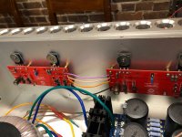
Your missing the thermistor on your problem channel, there should be one on each N & P channel PCB.
Your missing the thermistor on your problem channel, there should be one on each N & P channel PCB.
Good catch! 🙂
Yeah, I have some extras. I am going to remove that one and install a new one on the other board and see if there is any difference. I'm told it doesn't matter which spot you use, but worth a try.
I am lazy, I'd just pull 1 leg, you can solder it back from the top if needed...
Stupid question the resistor in series with the thermistor is the correct value and identical to the other channel ?
Stupid question the resistor in series with the thermistor is the correct value and identical to the other channel ?
Yes, I've checked the resistor values a few times against the schematic and the other channel. They are identical. And they measure close to perfectly.
Can you take close ups of the board with the mosfet acting up? Reason I ask is some of the solder joints I see in the pix in post #7 look like they're not flowing through on both sides of the boards. So perhaps solder could use a touch up.
If you measure the resistors are they showing 0R5 with the 1R's in parallel?
If you measure the resistors are they showing 0R5 with the 1R's in parallel?
They all show 0.7ohm, which I chalk up to my multimeter not being that accurate at lower levels. But they are consistent at .7 across all four sets on the problematic channel.
- Home
- Amplifiers
- Pass Labs
- F5 Turbo V3 - Help with uneven bias on N Channel