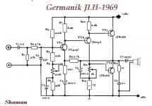
Translate the famous John Linsley-Hood's scheme to Germanium, at the output of GT806 and 1T813, changing the polarity in the scheme, a little finalizing you can get a wonderful sound. With amazing meander in 200 kHz.
Yes good point Diyers can translate some of the bipolars audio classics and modern designs into germaniums versions 🙂
E book https://ia801904.us.archive.org/32/...s and Low-Pass Amplifier Design (1968)-RR.pdf
@ Jpatay
Haha " Shaman " Thank You very much for schematic :^)
@ Diyers
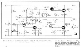
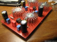
From Retronik archives class A 10 watt's hybrid amplifier
small signal are Germaniums+ BC107 are Si, power output stage are Silicon
Haha " Shaman " Thank You very much for schematic :^)
@ Diyers
From Retronik archives class A 10 watt's hybrid amplifier
small signal are Germaniums+ BC107 are Si, power output stage are Silicon
Attachments
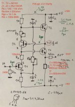
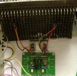
I made and tested this circuit for interstage transfrmer driver. Working very good even without thermal coupling and heatsinks at the output Ts. And stable, with 0mV offset. I am pretty sure that WITH thermal couplig of devices results will be even better and buffer will come to bias points faster...
I need higher input resistance. 240K used can be higher. Because of that I put JFETs at the input branch... AD161 are slight warm without heatsink, inspired of slightly higher current of 53mA cca. Bit R should be 2x2W or 5W single for not to overheat. Coupling C to the primary was 2200uF
.
I did this version first because I already had rest of the elements in place. BUT version with N-JFETs (2SK170 for instance) and AD162 (or other PNP more common Ge types) will also work. I will post schematic latter and build circuit theese days.
.
cheers
.
forgot to say that I tried same circuit from the picture with AC187 but with higher biasing resistor of 2K. Also working very good.
Attachments
Last edited:
2SB206 data sheet show max dissipation is 80 Watts
then other germanium smaller size transistors are 170 Watts.
How can this be possible? Germanium investigations
Maybe documentation error who underrated 2SB206.. any thoughts?
then other germanium smaller size transistors are 170 Watts.
How can this be possible? Germanium investigations
Maybe documentation error who underrated 2SB206.. any thoughts?
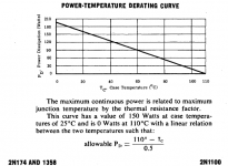
Yes, no doubt this is P dissipation formula
but look at the giant metal case size of 2SB206
logically with respect to the laws of physics small case can't dissipate twice of the heat.
Well, I don't know Ge chip size inside..
but repeat again data sheet of 2SB206 parameters are probably underrated.
Transistors producers factory use normaly big case only for large size semiconductor chip..
Usually the maximum power with a radiator is indicated. Power transistors have only a few watts of power without a heatsink. I shot a power of 3 W from the ГT402, with a radiator from an LED. Without heatsink, ГT402 collector continuous power dissipation: 300 mW.
Attachments
Last edited:
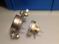
Well which one of the two transistors cases can dissipate more heat and handle higher temperature ?
Frankly I think the giant one is not two times less powerful
Can't believe old data sheet
Frankly I think the giant one is not two times less powerful
Can't believe old data sheet
Attachments
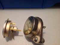
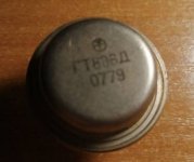
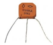
If the body of the transistor is larger, then without a radiator it will be several watts more.
Here the 1T910 transistor without cooling has 0.9 W, and the ГT806 in a large case has 2 W. But with a radiator 1T910 - 35 W, and ГT806 - 30 W.
If there is good thermal contact with the heatsink, then the transistor can be in a smaller package. These early designs of transistors were in large packages.
Attachments
Thermal resistance junction to case
then thermal resistance case to heatsink & ambient air
are different on two transistors models..but 2N****
Ge looks too good and little overrated on the data imho
then thermal resistance case to heatsink & ambient air
are different on two transistors models..but 2N****
Ge looks too good and little overrated on the data imho
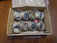
In a moment of excitement when I was on holiday a couple of weeks ago, I ordered 8 used 2SB206 on Yahoo Auctions Japan for cheap which Google translate said were classed as "junk".
Not expecting much for when they arrived, I played around with a curve tester on them (they aren't dead yet!) and got the Hfe and Vbe data to see how close they looked. If that's of any interest or someone is interested in seeing a graph let me know, more than happy to do a bit of measuring.
Next on the list is a SIT amp but after that, it'd be nice to put some of these into something and see how they sound, they look very cool 😀
Attachments
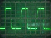
I replaced IRFP150N with Sziklai (KT961A / 1T813) in the circlotron. The power supply contains Д303 germanium diodes. At the output of the amplifier there are 1T813 germanium transistors. The sound came out much better than on Mosfet. I listened to the amplifier for two hours at low volume. The 250mA current was stable. And this is without a temperature sensor. Square wave - 32 kHz. In general, I'm a pervert. 😀
Attachments
Last edited:
- Home
- Amplifiers
- Pass Labs
- Germanium investigations