I have a pair of Hypex NCore 400 mono block kits headed my way. It would be super cool to have an analog VU meter on a custom front face. I would only want to do this if it can be implemented without any degradation to the amp's performance.
As a machinist and woodworker, a custom face plate wouldn't be a problem. I'm also competent with a soldering iron. But an electrical engineer I AM NOT. So in classic forum fashion... "Where do I go, what do I do?"
Thanks, J
As a machinist and woodworker, a custom face plate wouldn't be a problem. I'm also competent with a soldering iron. But an electrical engineer I AM NOT. So in classic forum fashion... "Where do I go, what do I do?"
Thanks, J
A V/U meter if used on the input side, would have a buffer so not draw any 'power' from the signal.
If the V/U meter is used on the output (across the speaker essentially) it makes no difference to the signal as you are, in both cases, measuring the signal voltage.
If the V/U meter is used on the output (across the speaker essentially) it makes no difference to the signal as you are, in both cases, measuring the signal voltage.
Eh ahem... some Class D amplifiers, if not most, have outputs that have no reference to Audio GND so connecting a VU meter to their outputs is somewhat more complex...certainly as a VU meter normally makes use of an electronic circuit that has a Audio GND connection...
In other words, Speaker - (minus) is NOT Audio GND in such cases...and connecting Speaker - to Audio GND is a short circuit of sorts.
In other words, Speaker - (minus) is NOT Audio GND in such cases...and connecting Speaker - to Audio GND is a short circuit of sorts.
Last edited:
Back in the olden days, Radio Shack sold a passive analog watt meter, Realistic APM100. Something similar should work.
This is an old post but it's exactly what i'm hoping to do. https://www.diyaudio.com/forums/class-d/87913-class-amp-photo-gallery-77.html#post3584650
I "think" I've seen the boards on ebay but don't know enough to say. Am I on the right path?
I "think" I've seen the boards on ebay but don't know enough to say. Am I on the right path?
These appear to be them:

Search for "TA7318P Driver Board For VU Meter"
Since they are shown with an NC400 module, I'd assume they are safe, but I'd like to confirm they are not grounded re: jean-paul's warning.
Search for "TA7318P Driver Board For VU Meter"
Since they are shown with an NC400 module, I'd assume they are safe, but I'd like to confirm they are not grounded re: jean-paul's warning.
I have had great success driving different meters with Rod Elliott's P55:
VU And PPM Audio Metering
I first modded four NISSEI TR-35 for an active filter, you can read all about it here:
Modding the NISSEI TR-35 VU Meter Part 1.
Modding the NISSEI TR-35 VU Meter Part 2.
It worked great but I wanted something BIGGER so I am now working on this:
Go Big or Go Home
VU And PPM Audio Metering
I first modded four NISSEI TR-35 for an active filter, you can read all about it here:
Modding the NISSEI TR-35 VU Meter Part 1.
Modding the NISSEI TR-35 VU Meter Part 2.
It worked great but I wanted something BIGGER so I am now working on this:
Go Big or Go Home
Last edited:
These appear to be them:
View attachment 942703
Search for "TA7318P Driver Board For VU Meter"
Since they are shown with an NC400 module, I'd assume they are safe, but I'd like to confirm they are not grounded re: jean-paul's warning.
Thank you Net David. Far as I can tell it's wired as in my picture except there are some resistors to get from the 18v on the SMPS600 to 12v required for the board.
As a protein chemist, once the electrons leave their respective molecules, I have to fall back on my high school physics class. And I get how frustrating it can be when someone stumbles in from the internet with his mouth open and his hand. Out. Your feed back is appreciated. Cheers, J
Attachments
I have had great success driving different meters with Rod Elliott's P55:
VU And PPM Audio Metering
I first modded four NISSEI TR-35 for an active filter, you can read all about it here:
Modding the NISSEI TR-35 VU Meter Part 1.
Modding the NISSEI TR-35 VU Meter Part 2.
It worked great but I wanted something BIGGER so I am now working on this:
Go Big or Go Home
I've enjoyed reading some of your blog EmuMannen, great work!
jean-paul is right. Rod Elliott's P55 supports two options, speaker level (stay away from it if you don't know exactly what jean-paul is talking about) and line level. Use line level on the input side if you don't want to use speaker level. If you know the sensitivity of your power amp it is also easy to use the VU-meter as an indicator of headroom before clipping.Eh ahem... some Class D amplifiers, if not most, have outputs that have no reference to Audio GND so connecting a VU meter to their outputs is somewhat more complex...certainly as a VU meter normally makes use of an electronic circuit that has a Audio GND connection...
In other words, Speaker - (minus) is NOT Audio GND in such cases...and connecting Speaker - to Audio GND is a short circuit of sorts.
This referring to "TA7318P Driver Board For VU Meter" or VU meters in general? I see no reason why not in either case.Any idea if this will this work with the Icepower 50ASXBTL amps?
I can not speak for the quality of the TA7318P Driver Board because I have not tried it myself. But I have tried a bunch of similar boards and if you just want "the needle of which swings quickly and is responsive" as stated about the TA7318P Driver Board then it might be enough. But I personally prefer Rod Elliott's P55 because of the quality of the needle movement and the PPM mode. Your mileage may vary.
The TA7318P Driver Board supports both line level and speaker level. The Icepower 50ASXBTL comes as both SE and BTL, right? Just keep in mind what jean-paul stated if you run it in BTL mode and plan to use speaker level.
Which way would be best for me to run in?This referring to "TA7318P Driver Board For VU Meter" or VU meters in general? I see no reason why not in either case.
I can not speak for the quality of the TA7318P Driver Board because I have not tried it myself. But I have tried a bunch of similar boards and if you just want "the needle of which swings quickly and is responsive" as stated about the TA7318P Driver Board then it might be enough. But I personally prefer Rod Elliott's P55 because of the quality of the needle movement and the PPM mode. Your mileage may vary.
The TA7318P Driver Board supports both line level and speaker level. The Icepower 50ASXBTL comes as both SE and BTL, right? Just keep in mind what jean-paul stated if you run it in BTL mode and plan to use speaker level.
I would run it in line-level mode, in parallel with the inputs. I.e., left meter + connected to Signal header P102 pin 7 (if you use channel 1 as the left channel) and meter -/GND to pin 6, right meter + connected to Signal header P102 pin 4 (if you use channel 2 as the right channel) and meter -/GND to pin 5.Which way would be best for me to run in?
Next question, what do you want the meters for? If you only want "dancing needles” then calibrate to whatever looks nice. If you want to use it as a VU-meter, connect a signal generator and calibrate the meters to show 0 dB for a 1kHz signal @ 1.228 VRMS. If you want it as a meter of headroom before clipping, deduct 3 dB from your input sensitivity and calibrate 0 dB for whatever VRMS that would be. E.g., it seems like the input sensitivity of the ICEpower 50ASX2BTL is 3.3 Vp, that equals 2.33 VRMS. -3 dB equals 1.65 VRMS so calibrate the meter to show 0 dB @ 1.65 VRMS and you know you are 3 dB from clipping the input with 0 dB on the meter.
From the source:
.....Aan: Support | Hypex Electronics BV <support@hypex.nl>
Onderwerp: Re: Read more...
May I hook an ordinary oscilloscope to the output of a NC400 amp
....
Hi,
The speaker negative is at ground potential so it should be fine.
Kind regards,
- - - - - - | Hypex Electronics BV | Technical Support Engineer
//
I guess it is for a SE NC400 but there are apparently Hypex NCore NC400BTL bridged tied load mono blocks out there and the Icepower 50ASXBTL is also in bridged tied load. I’m not saying you can’t hook up a VU meter or an oscilloscope over a BTL but you sure need to know what you are doing and what you are measuring. Short-circuit the two output poles of a BTL is usually not recommended.From the source:
I would run it in line-level mode, in parallel with the inputs. I.e., left meter + connected to Signal header P102 pin 7 (if you use channel 1 as the left channel) and meter -/GND to pin 6, right meter + connected to Signal header P102 pin 4 (if you use channel 2 as the right channel) and meter -/GND to pin 5.
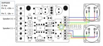
Maybe I should have been even more explicit regarding the TA7318P Driver Board and the Icepower 50ASXBTL? First channel; Signal header P102 pin 7 to LOW on TA7318P board. Signal header P102 pin 6 to GND (next to LOW) on TA7318P board. Next channel; Signal header P102 pin 4 to LOW on TA7318P board. Signal header P102 pin 5 to GND next to LOW) on TA7318P board.
Middle +/- connectors (red/green lines in picture) from TA7318P board to one meter and middle +/- from the other connector (red/green lines in picture) to the other meter. Outer V+/V- connectors (blue/yellow lines in picture) can be used to feed the meters backlight (if it got one). Note the power output seems to be 12V so you might have to add resistors if the backlight is a LED (or not a 12V bulb).
Use W1 and W2 to calibrate meter readings…

Last edited:
From the source:
.....Aan: Support | Hypex Electronics BV <support@hypex.nl>
Onderwerp: Re: Read more...
May I hook an ordinary oscilloscope to the output of a NC400 amp
....
Hi,
The speaker negative is at ground potential so it should be fine.
Kind regards,
- - - - - - | Hypex Electronics BV | Technical Support Engineer
//
Thank you for confirming TNT. I'm going to push forward with the plan I laid out a few posts ago. Cheers, J
- Home
- Amplifiers
- Class D
- VU meter in an NCore400?