Anyone already working on a tube front end yet?
Something like this?
dave
Nelson, hope it is alright to use your X?
Attachments
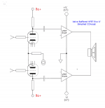
I think the VFET is a design that already has a “tube like” sound quality already, adding a tube front end is perhaps like a bit too much sweetener in your favorite recipe. Also, making it a BTL (“x” or balanced) output amp will cancel out even order distortion and make it more odd-order dominant distortion. If that’s the sound one likes, I guess it’s fine.
However, will not placing such a large electrolytic capacitor in the output signal path negatively offset some linearity this transistor is known for? Again, I'm assuming this is to keep costs down, as designing a push pull class A version using these devices would easily triple the cost.
Not looking to start a debate, Just wanting to get some feedback from the group regarding this.
The short answer is “because the amp uses a single-rail power supply.”
It doesn’t affect the linearity of the Vfet at all.
This is great information -
SYclotron Audio | Why are people obsessed with coupling caps?
Some of the best sounding amps I have heard use a big electrolytic output cap and they measure quite well too. Don’t fear cap coupled output amps. Plus, it provides DC protection for your expensive and fragile 95dB speakers. 🙂
I think the VFET is a design that already has a “tube like” sound quality already
I hate the term "tube-like". I take it to mean a badly designed tube circuit. A good triode is one of the most linear amplification devices we have. A well designed stage should be very neutral, have lots of swing, and high DDR.
No "tube-like" please.
dave
In my mind, “tube like” means dominant second harmonic, a bit of third, not much else and THD around 1%. I think the VFET amp is sort of described by this. So adding a SET tube front end will just be adding more THD and more H2 and H3 and it may be laying it on a bit too much.
I don’t hear anyone else referring to “DDR” of a tube amp. If you mean resolving detail and having low distortion, a state of the art solid state opamp like OPA1656 will be tough to beat.
There is the nano vacuum channel transistor (NVCT) (a filament-less SET that is like a vacuum tube but operates by having electrons fly across a 40nm gap (smaller than mean free path) so that even ambient pressure is considered a “vacuum”). The NVCT can operate up to 400GHz so is very high speed. Unfortunately, still researchy “one of a kind” prototypes.
Nanoscale vacuum channel transistors fabricated on silicon carbide wafers | Nature Electronics
Last edited:
DDR was a term coined by a very skilled tube circuit designer.
One of the things people like about really good tube gear is its high DDR.
dave
One of the things people like about really good tube gear is its high DDR.
dave
"In my mind, “tube like” means dominant second harmonic, a bit of third, not much else and THD around 1%"
this is a perfectly fine description of "tube like", I like it.
Planet10- you criticize "tube like" then use a term like "DDR", hmm...
this is a perfectly fine description of "tube like", I like it.
Planet10- you criticize "tube like" then use a term like "DDR", hmm...

After 10 days of digesting I got to admit defeat. My understanding is that a P-channel common drain square law device loaded with a current source should have a negative phase H2, but Papa said in diy_part_1 the J28 was doing positive. 😕not 100% sure about, I think sole difference could be phase of 2nd
I hate the term "tube-like". I take it to mean a badly designed tube circuit. A good triode is one of the most linear amplification devices we have. A well designed stage should be very neutral, have lots of swing, and high DDR.
No "tube-like" please.
dave
agree 100%
OK, it is not outrageosly linear ...... I mean - with care it is
point is - when I'm content with tube stage I made, nobody could tell is it tube or something else, if not being able to peek under the lid
....
see- that's why I'm not even bothering with phase
as Homer would say, after head is starting to ache - "hm....... Beer!"

After 10 days of digesting I got to admit defeat. My understanding is that a P-channel common drain square law device loaded with a current source should have a negative phase H2, but Papa said in diy_part_1 the J28 was doing positive. 😕
see- that's why I'm not even bothering with phase
as Homer would say, after head is starting to ache - "hm....... Beer!"
One member asked if he could return his winning ticket for the first batch and then take his chance on the 2nd draw (N-channel)... This is perturbing me since.. but I am easily perturbed anyway😕
Right, wizards, prophets and saints can do that. Common folks can't drink solid ice nor walk on liquid water.... not even bothering with phase
Right, wizards, prophets and saints can do that. Common folks can't drink solid ice nor walk on liquid water.
when listening Caruso 8-cd set, phase is not influencing number of tears
🙂
Something like this?
Thinking about one anyway but more along the lines of SE to PP interstage. Edit: Or... a floating paraphase because easy to tune in missing H2
Last edited:
My loudspeakers are 12 ohm impedance
Spatial Audio M4 TM,s so I’m wondering if the amplifier would respond with a wattage greater than 10w...
Spatial Audio M4 TM,s so I’m wondering if the amplifier would respond with a wattage greater than 10w...
it'll sing
though, from my experience with limited OB size, going with separate (more potent) amp for bass helper is clever move
though, from my experience with limited OB size, going with separate (more potent) amp for bass helper is clever move
Folks:
A dumb question, perhaps, but how much capacitance would you recommend for a linear power supply for this VFET amp? I am contemplating a CLC or CLCRC supply and was imagining something on the order of 100,000 uF, but I have no experience with VFETs and limited experience with low-powered amps.
Thanks for the input!
Regards,
Scott
- Home
- Amplifiers
- Pass Labs
- DIY Sony VFET pt 1