im new to amp repair as far as getting into reading component values and undersanding how it actually works.. i have an cheap oscope but not sure how to really use it..
so i have a hifonics brutus 2016.1d that powers up but has no sound except a loud pop when i turn off the power.. thinking about it this it might be cuz im just cutting the power supply and not turning off the remote first.. ill try that next time..
1 side of output fets read 77.5 volts on the drain and the other side reads 77.5 volts on the gate and source is that normal?
i found a chip on the driverboard was burnt so i ordered a new one based on what i found online was chip lm211 and it was a bit larger than the one on the board.. i put it on anyway.. i know not the right move im sure but what should i be checking and whats the correct part to order?
Are you saying that the LM211 actually burned?
Photos of what you currently have?
What scope make/model? Link to its owner's manual?
Photos of what you currently have?
What scope make/model? Link to its owner's manual?
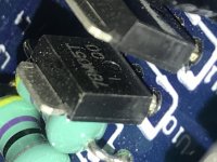
yes the lm211 had a raised white spot on the chip.. model was not readable on the chip itself and google was giving unsure results so i cross referenced driver board on another amp that matched 2 out 3 chips so i figured would be a good assumption to go 3 for 3 and say was lm211.. the one i ordered said lm211 but reads lm211n and is twice as big as you can see..
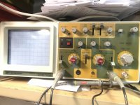
my scope is a 25mhz BK Precision model 2120b.. the only manual i found says its a 2120b but a 30mhz.. it looks like the right one it matches the one in the picture. i dont know what anything really does.. i was able to adjust the probe to get a good square wave and can get the line to move around reading some voltages but nothing i could make sense of..
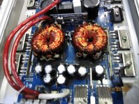
a little more background on the amp i forgot to mention.. i replaced all the power and output mosfets and a few resistors around the what i think is the transformer.. i had to pull the rail right next to it to get to it and it had appeared like the transformer itself was burnt on the bottom so pulled it and checked it but was fine.. was just soot from the nearby resistor burning. reading online said larger resistors are ok to use but not smaller. in physical size, property value still has to match.
my scope is a 25mhz BK Precision model 2120b.. the only manual i found says its a 2120b but a 30mhz.. it looks like the right one it matches the one in the picture. i dont know what anything really does.. i was able to adjust the probe to get a good square wave and can get the line to move around reading some voltages but nothing i could make sense of..
a little more background on the amp i forgot to mention.. i replaced all the power and output mosfets and a few resistors around the what i think is the transformer.. i had to pull the rail right next to it to get to it and it had appeared like the transformer itself was burnt on the bottom so pulled it and checked it but was fine.. was just soot from the nearby resistor burning. reading online said larger resistors are ok to use but not smaller. in physical size, property value still has to match.
Attachments
You ordered a DIP package. You needed an SOIC.
What is the DC voltage on terminals 4 and 8 of the LM211?
Read pages 20 and 73 of the following site, even the parts that you feel are irrelevant.
Basic Car Audio Electronics
What is the DC voltage on terminals 4 and 8 of the LM211?
Read pages 20 and 73 of the following site, even the parts that you feel are irrelevant.
Basic Car Audio Electronics
reading pin 4 at -3.88v and pin 8 at 4.56v
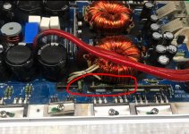
theres 3 white blocks in the center of the board and the middle ones gets pretty hot after a min or two.. ive read those pages and they help a little hut im working on reading more as i find time..
theres 3 white blocks in the center of the board and the middle ones gets pretty hot after a min or two.. ive read those pages and they help a little hut im working on reading more as i find time..
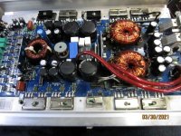
Post a high resolution image of the entire main board.
How many header pins does the audio driver board have?
How many header pins does the audio driver board have?
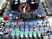
board labeled "MC 1200.1D (B)PCB-A02"How many header pins does the audio driver board have?
has two connectors 6 pins on one side 8 pins on the other total 14 pins
Attachments

What are U10 and U11 at the end of the driver board?
Have you worked with your scope any more since reading the scope page?
Have you worked with your scope any more since reading the scope page?
What are U10 and U11 at the end of the driver board?
Have you worked with your scope any more since reading the scope page?
i played with it a little bit and am able to get a wave reading the output transistors but its more like a bad heart reading machine wave.. kinda jagged and uneven.. still playin and reading more about it..
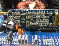
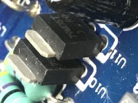
heres u10 and u11
Attachments
so if they work like a mosfet transistor with gate drain and source this is what i getPost the DC voltage on all 3 legs of both of those regulators.
DC gate | drain | source
U10 15.34 | 0 | 5
U11 0 | -14.8 | -5
post doesnt keep format but think its close enough to understand
andni have played with the scope a bit more and figured how to read the wave signal coming into the amp using a tone generator so that was exciting lol
Last edited:
In the future...
Post the voltage readings precisely as displayed on your meter. If it's 4.95, post 4.95, not 5.
Post readings vertically like this:
Pin 1: <note colon and space>
Pin 2: reading x
Pin 3: reading y
Pin 4: ...
These are not like FETs. They are voltage regulators. The pins are:
LM78M05
Pin 1: input
Pin 2: ground
Pin 3: output
https://www.ti.com/lit/ds/symlink/l...17567&ref_url=https%3A%2F%2Fwww.mouser.com%2F
LM79M05
Pin 1: ground
Pin 2: input
Pin 3: output
https://www.mouser.com/datasheet/2/149/LM79M05-461616.pdf
Why do you have -3.88v on pin 4 of the LM211 when there is -5v on the regulator?
rechecked the readings and this is what i got
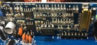
U10: 78MO5T
Pin 1: 15.39
Pin 2: 0.00
Pin3: 5.00
U11: 79MO5T
Pin 1: 0
Pin 2: -14.82
Pin 3: -5.08
LM211
Pin 4: -5.07
Pin 8: -4.58
and not sure if i said this before but one of the white rectangular blocks in the center of the board next to the relay gets pretty hot.. 179° F if thats considered hot or not for electronics.. way hotter than any other part of the board which was around 90°F
and i ordered the correct LM211 soic chip should be here tomorrow..
Last edited:
The difference between -3.88 and -4.58 is significant. What happened between measuring the voltage to make the readings so different?
Now measure the DC voltage on U12 at the other end of the board. Place the black probe on the center leg and post the voltage on the other 2 legs.
To get some practice with your scope, post the gate and drain waveform from one of the PS FETs.
Go back to the oscilloscope page of the site and read the 'best initial settings' and study the large white graphics image.
Oscilloscope
Hi there. I know it's been a loooong time and an old tread, but here we go.
The ic U3 (LM211N) did you get it to work?
The ic U3 (LM211N) did you get it to work?
Last edited:
- Home
- General Interest
- Car Audio
- Hifonics BRX2016.1D no sound