Maybe I'm taking the wrong approach, and I'm thinking it would be better to let you carry on. Just make sure that the procedure you're reading fits your situation.
It might be better to approach issues as you come across them.
It might be better to approach issues as you come across them.
Thanks, Allan. I know it's frustrating from your side. For me a little explanation goes a long way. Once I get it, I get it, and I can work the problem.
My original issue was understanding phase traces, and you were very helpful. Really turned the light bulb on there. After working with PCD a little bit more, I attached a new screenshot (a few posts ago). Comparing that one to the original, does it look like I'm at least on the right track relative to manipulating phase alignment?
My original issue was understanding phase traces, and you were very helpful. Really turned the light bulb on there. After working with PCD a little bit more, I attached a new screenshot (a few posts ago). Comparing that one to the original, does it look like I'm at least on the right track relative to manipulating phase alignment?
Thanks, it's not that, but I need to stand back and recalibrate my advice. I'm also not familiar with the nature of the diffraction simulator you are using but that's not my main concern.
You did make some apparently deliberate manipulations of phase that I can see. It is easy to learn when there is not a time difference between the responses. Not that time differences are a problem, just more difficult to make filters for.
You did make some apparently deliberate manipulations of phase that I can see. It is easy to learn when there is not a time difference between the responses. Not that time differences are a problem, just more difficult to make filters for.
Steve, I'd offer to help, but after pointing you to the Smaart manual ala phase traces, that's as close to IIR/passive crossovers as I want to get. They are crazy complicated and unwieldy nowadays (for me). I admire those that master them. Good luck !
Thanks, Allan
I was taking your comments under the assumption that you were familiar with Bagby's Response Modeler and PCD, which was creating some cross-talk in my little brain. No worries. If you wanted to look at it, the download is easily found with a search (or I could post a link). It's a free, Excel based program. I'm going to do a little more research on minimum phase to see if I can determine whether or not I should be applying that module of the program to the manufacturer's data I'm throwing at it.
I was taking your comments under the assumption that you were familiar with Bagby's Response Modeler and PCD, which was creating some cross-talk in my little brain. No worries. If you wanted to look at it, the download is easily found with a search (or I could post a link). It's a free, Excel based program. I'm going to do a little more research on minimum phase to see if I can determine whether or not I should be applying that module of the program to the manufacturer's data I'm throwing at it.
Steve, could you zip the drive response files (frd's, zma's, crossover schematic (pcd screen shot)), baffle measures? Perhaps it would make things easier to check.
Baffle diffraction response module of RM calculates only diffraction response for one driver at a time, and the coordinates that you enter serve only to define the diffraction. If you instruct PCD that Y coordinate is zero, then it assumes your driver is a co-axial unit.
Thanks, Lojzek.
Understood on both points. I will reinsert the Y axis dimensions. I've been assuming that using the highly modified FRD and ZMA files from RM, and positioning the drivers in both programs might introduce unwanted phase corrections. (This was much simpler before I discovered RM. But again, I'm trying to get the most accurate result possible, without the benefit of testing gear).
Understood on both points. I will reinsert the Y axis dimensions. I've been assuming that using the highly modified FRD and ZMA files from RM, and positioning the drivers in both programs might introduce unwanted phase corrections. (This was much simpler before I discovered RM. But again, I'm trying to get the most accurate result possible, without the benefit of testing gear).
Steve, could you zip the drive response files (frd's, zma's, crossover schematic (pcd screen shot)), baffle measures? Perhaps it would make things easier to check.
Well, it's been a work in progress for months, so I've developed a bunch of different scenarios, and the crossover schematics for each don't stay still for long. I've still got tweaking and corrections to do, or I wouldn't be here. But I'll fix up one I like and share it with you. Is it the raw driver FRD and ZMA files you are interested in, or the modified files coming out of RM?
Send the raw files and all additional information needed to complete the design as you want it so we'll be, hopefully, able to compare results. Fir example, If you wanted a certain volume of enclosure for the woofer only, then please specify so, etc... and I'll manipulate the data.
Here you go, Lojzek. Thank you for volunteering your help.
As stated in the beginning, this is a redesign of my existing kit system. It is over 25 years old. A photo of the existing is included. The midrange drivers will be replaced with much better units. The tweeters will be rebuilt with dome/coil replacements. The bass units were replaced about 8 years ago, so keeping those. They are dual 8 ohm voice coils, that are wired series/parallel for a nominal 8 ohms together. Assume them to be 4 ohms each.
Boxes are 1" MDF with some internal bracing. (Heavy). They are 11.25" wide x 50.75" tall x 14.75" deep. Bass volume is 78L, vented, with (2) 2" diameter x 4" long vents flared both ends. This is not the optimal volume for these bass units. They want more volume in a vented system. But then they'd be huge. This is reasonable compromise, and still capable. The two midrange drivers and tweeter are in an enclosed chamber of 6L.
Target crossovers are 300 and 2400. 2400hz is an octave below were the midrange off axis dispersion really kicks in, and also far enough down were the 4th order low cross puts the mid's 10k cone breakup 30db down. Target FR is between 85 and 89 db with a bias towards the low end.
Ask me anything. Nothing is off the table. I never intended for anybody to design this thing for me, by bringing my initial question to the forum, but your help and coaching is very much appreciated.
Thanks, again.
Lojzek,
I forgot the baffle information:
Drivers will be flushed this time around. Baffle is 11.25"x 50.75". All drivers are centered on baffle. W1 at 19.5". W2 at 27.75". M1 at 35.25". T at 40.25". M2 at 45.25".
And a word regarding the midrange low pass: The example I sent uses a 4th order LR for reasons mentioned. In some of my models I used a 2nd order with notch filter, which knocks the cone break down, but seemed a littler harder to work with for me.
Thanks, again, Lojzek.
Thanks. Peerless units being 8.68" of overall diameter are overlaping each other being separated by the 8.25" distance (27.75-19.5).
Last edited:
Good catch. Mis-measured. W1 should be 18.75". W2 should be 27.5". Maybe an 1/8" gap between the woofers where they come together.
Steve, I'd like you to try a tweeter hp filter consisting of 5R1; 6u8; 0,33mH (dcr 2.2 or same resistor) and 10uF. I got it to appear as LR4 which yields a better phase tracking to midrange units. It is a 3rd order electrical filter with a series resistor before the hp.
Thanks, Lojzek
Let me make sure I fully understand. First, should I delete all other HP elements, including the RLC after cross, and the resistor I have on the C9 cap?
Then I am putting a 6uf (or is it a 6.8uf) in position C9, 0.33 inductor in position L9, a 10uf cap in position C10, a 2.2 DCR on the 0.33 inductor, and a 5ohm series resistor before the cross.
Is that all correct?
Correct, your filter parts are to be deleted, then the new ones to be added in order you have said. 6u8=6.8uF. And put the minus sign before the values of each Z offset.
Attachments
Last edited:
Something to consider in order to further improve the simulation a bit
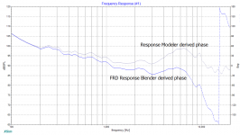
This graph represents phase plots only of one and the same driver, upper midrange unit, which was calculated with different pieces of software. The more accurate one is achieved with FRD Response Blender because it offers to extend the FR tails. You only need to correctly foresee how the falling tendency of the FR is to be expected within FRD Blender. It is easy enough to perform one, you upload the frequency and magnitude data in the HF FRD data, the third tab of Blender, and switch to Control tab where under step 4 you can define the slopes. After that, hit extract minimum phase and then save blended result to frd file.
In case import frd data on tab HF FRD data won't comply, copy/paste manually the data to columns A and B through a text editor of some sort.
Attachments
Thanks, Lojzek
I think I also need to invert the tweeter - correct? So normal woofer, and inverted midrange and tweeter.
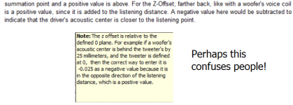
Yes the Z offset thing is totally confusing, since your screen shot says it both ways. I've been aware of the conflict the whole time I've been using PCD, but opted to go with the instructions actually attached to the spreadsheet. My sense is that Bagby switched it somewhere along the version progression, but now the documentation is inconsistent. Now switching to negative - every model I've done is wrong. Arghh.
I don't know if it is the same thing, but I see RM has a function to apply slopes to either end of each driver, but I didn't know how to use it, so left it alone. What frequencies and slopes did you use. I will try to wrap my head around FRD if it is the better system.
I think I also need to invert the tweeter - correct? So normal woofer, and inverted midrange and tweeter.
Yes the Z offset thing is totally confusing, since your screen shot says it both ways. I've been aware of the conflict the whole time I've been using PCD, but opted to go with the instructions actually attached to the spreadsheet. My sense is that Bagby switched it somewhere along the version progression, but now the documentation is inconsistent. Now switching to negative - every model I've done is wrong. Arghh.
I don't know if it is the same thing, but I see RM has a function to apply slopes to either end of each driver, but I didn't know how to use it, so left it alone. What frequencies and slopes did you use. I will try to wrap my head around FRD if it is the better system.
- Home
- Loudspeakers
- Multi-Way
- Checking phase alignment for 3-way crossover