Thanks!
Yes, just flippped this switch a few times.
Hiss is loud on MC setting, not so much on MM... maybe this is a normal for this amp?
Yes, just flippped this switch a few times.
Hiss is loud on MC setting, not so much on MM... maybe this is a normal for this amp?
The output Of MC cartridges is only about 10% of the MM type so the gain of the preamp in MC mode is proportionally higher. With the gain increase, the noise to signal ratio will usually increase to some degree too, so there needs to be high quality, low noise electronics tailored to both cartridge types but the MC section needs to be specially good - at least a whole lot better than typical MC preamps of the 1970s.
In a nutshell, if you want to really enjoy using MC phono cartridges in the 21st century, its going to cost a small fortune. In any case, unless you use the best and quietest preamps you can afford, you'll be forever concerned with how noisy vinyl is compared to digital sources and so on.
In a nutshell, if you want to really enjoy using MC phono cartridges in the 21st century, its going to cost a small fortune. In any case, unless you use the best and quietest preamps you can afford, you'll be forever concerned with how noisy vinyl is compared to digital sources and so on.
Cheers Ian, this makes sense.
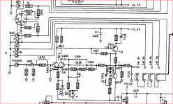
Does it follow that swapping those few ceramic discs in the 3020A phono/pre path, as per the photo, might be a good idea?
Does it follow that swapping those few ceramic discs in the 3020A phono/pre path, as per the photo, might be a good idea?
Fully appreciate that the 3020A has it's limitations, but in the period between now and procuring something a clear step up I'd like to have the 3020A perform at it's optimum.
But would the change to mkp, pfr, phe, or MLCC's likely be a step towards this?
But would the change to mkp, pfr, phe, or MLCC's likely be a step towards this?
If I was going down the MC route, I'd seriously consider step up transformers and using MM inputs. Or possibly a diy job ( phono stage ) feed by a solar cell ( like Denson do ) .
Last edited:
The problem with signal transformers for MC is interference - double mu-metal screening cans are sometimes used to mitigate this, which can get pretty expensive. To me the logical approach is a head-end preamp in the cartridge shell itself so no low-level signals have to brought out. The various designs where the headshell is basically a PCB with preamp on it appeal to me as a clever way to do this.
Fully appreciate that the 3020A has it's limitations, but in the period between now and procuring something a clear step up I'd like to have the 3020A perform at it's optimum.
But would the change to mkp, pfr, phe, or MLCC's likely be a step towards this?
Looking at the parts list some of the components in the RIAA feedback network have capacitance tolerances of +/- 50%.
Hmm - the low value Ceramic types are +/-10%. These could be NP0 types having a segment of black at the top of the front face.
Some capacitors have values outside of the standard ranges will be hard to source.
NP0 are Class 1 types which are OK but any ceramic in Class 2 or 3 should not be used in a signal path.
Re your hiss did you replace C410 and C408 and equivalents in the other channel as part of your recap - the former decouples the LTP negative supply to earth and the latter decouples the nfb arm to earth.
The the quality of both capacitors and their connection to ground is important.
Attachments
Last edited:
Back at #17, your query about hiss was in regard to a different levels in either channel. Did you resolve that or is it still a problem?
Hi Ian.
Thanks for asking. Yes, still at different levels in each channel.
Apologies as I'm jumping about somewhat. I'd like to check and maybe adjust bias and probably fit some Bourns trimmers. However, I think I read a post in which you discussed how this amp can sound best when the balance is 'unbalanced,' maybe 35mV in one channel and 55mV in the other.
At the moment I have no idea what the bias now is after all the recapping and have the Bourns replacements to hand. Worth fitting them taking readings and decide what level to then set bias at?
Thanks Mjona, yes, C410 and C408 were replaced but connections are both good.
Now planning on putting in some replacements for the ceramic disc caps, good point.
Now planning on putting in some replacements for the ceramic disc caps, good point.
I can't think why I would have made a remark like that. I should have been clearer because I would have meant to say that precise DC offset voltage is unimportant. Within limits, it becomes an OCD matter but as a factory or servicing setting, it's no more difficult to set it as close to zero as possible than anywhere else. So adjusting offset to zero is all fine and textbook but don't obsess over it when you see insignificant errors..... I think I read a post in which you discussed how this amp can sound best when the balance is 'unbalanced,' maybe 35mV in one channel and 55mV in the other....
OTOH, if your amplifiers are direct coupled to the drivers in an active crossover speaker system, offsets do become very important for the HF drivers but actives are not your typical commercial loudspeakers.
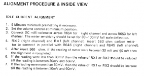
Hi Ian, my apologies, I should have written that I was needing to better understand idle current alignment procedure on this unit.
I thought that the following thread was informative as the OP relayed that his experience when trying to fine tune his unit in order to get the same reading on both channels led to the sound quality becoming dull and veiled. So much so that he ended up reinserting the original biasing resistors.
NAD 3020A Bias
Good to hear your reassuring view on precise DC offset voltage. FWIW my unit readily adjusted to zero on both outputs after the recap.
Thanks Mjona, yes, C410 and C408 were replaced but connections are both good.
Now planning on putting in some replacements for the ceramic disc caps, good point.
Ceramic caps have no significant aging issues and they have relatively low impedance at r.f. if you change these I think you will notice a difference but I don't see that resolving your hiss issue.
Ceramic caps are recommended for bypass duties in op.amps they are specified in datasheets to ensure stable operation of the particular IC. There are good reasons to use them in discrete component layouts too.
(Have to say that most of the pulled caps gave reasonably good readings on a cheap transistor tester.)
I question the wisdom and the expense of recapping this older gear unless it is clearly showing a fault. I have gear going back to the 70s still working fine.
Sadly the same cannot be said for much of the commercial gear made from the mid 2000s onwards. Most of the repairs I do are due to the flood of fake capacitors that hit the market.
Looks like you did a decent job enjoy.
Thanks everyone.
I've yet to link a turntable so will assess the hiss issue when I do.
In the meantime, I measured the idle current and, yes, it's
Left channel: 56.2mV
Right channel:36.2mV
Very similar to Corona Blue's measurements. Although I have Bourns trimmers to hand I'm tempted to leave the unit as it is for fear of reducing the SQ.
Question:
I desoldered the blobs in order to get these readings..
Do I need to resolder the blobs?
What would be the likely consequence of not resoldering the blobs?
I have typically replaced the bias and offset pots to 10T on that vintage of NAD - the single turns are sometimes blanketed with paint, and the wiper settings are often very twitchy. My 3020 was able to be setup for <1mV offset and effectively equal bias current levels on both channels. One aspect of not being able to get to nominal settings is that something could be degraded in the circuitry somewhere.
Perhaps read a few forum threads on any similar NAD to find out what happens when someone forgets to resolder the bridge.
I was keen enough to add base and emitter resistors for the output stage bjt's, to alleviate a common form of failure mode.
Perhaps spend some time to set up a soundcard or similar digital interface so that you can test the performance of your amp, and not so much rely on your ears for picking up subtle problems. Standard software like REW allows the amp to show it has low noise floor and distortion across the frequency spectrum, and no hidden gremlins.
I agree with mjona in post #18, it is unwise to naively modify the main filter caps - that can be one step forwards and 2 steps back.
Last edited:
According to the service manual I read, if the bridge was not re-soldered the amplifier would fail.
Bournes trimmers fitted and dialling in the 'factory set' unbalanced settings.
Was easily achieved. Sounds very good at this point.
About to try changing the ceramic disc filters in the pre-amp section to the following.. would welcome any constructive comment..
2990774 5 RDE5C1H470J0M1H03A CAP, 47PF, 50V, MLCC, RADIAL RDE5C1H470J0M1H03A
2990778 5 RDE5C1H680J0M1H03A CAP, 68PF, 50V, MLCC, RADIAL RDE5C1H680J0M1H03A
2990741 5 RCE5C1H221J0DBH03A CAP, 220PF, 50V, MLCC, RADIAL RCE5C1H221J0DBH03A
25291631SMR5104J100J03L16.5CBULK CAP, 0.1µF, 100V, 5%, PPS,RADIALSMR5104J100J03L16.5CBULK
- Home
- Amplifiers
- Solid State
- NAD 3020A recap assessment