Hi,
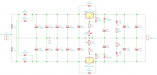
I have built a dual linear power supply based on the LM317/337 to provide +-12V from a toroid transformer.
If I connect to the positive rail a 10R resistor to the positive rail, the output voltage is 11.6V, if I connect a 15R resistor, the output voltage is 11.8V, for both in series, it is 12.0V (I have tuned the output voltage with those in series).
Does the LM317 really have this poor load regulation?
Further, when connecting both resistors in series (25R, i.e. 480 mA), I get an input ripple of 288mV, and an output ripple of 25mV.
Shouldn't that be much lower? The datasheet of my particular LM317 says 60-80db ripple rejection at 120Hz (I have 100Hz)
The schematic is attached.
Have I messed something up in the schematic?
Attachments
The regulation should be excellent so something is amiss.
First check has to be that the input voltage including ripple when under load is always above the minimum required for regulation. That means you need 3 or 4 volts headroom at least.
Physical layout and how things connect is important. The 240 ohm should connect directly to the regulator pin and not at some place further down the line, be that PCB print or wire. You must measure the output voltage at the regulator itself, between the output pin and the lower end of the resistor network. Anything else and you see errors due to wiring resistance.
There is a minimum load current specified for the LM317 which is normally met by the resistor setting network. I think it is around 5 milliamps.
Do you really need nearly an amp of load current? Test with the actually needed load instead.
Input voltage ripple is ( Iload x 8.3mS / C ).
Input voltage ripple is ( Iload x 8.3mS / C ).
Last edited:
Also note the fine detail of how you have hooked-up the regs really, really matters.
Your R3 and R4 connections to pin 2 are ideally right at the regulator body- not down near the output connector. Similarly, for both rails, the connection of RV +its 10uF bypass cap to 0v should as close as possible to the output connector 0v - not on the shared impedance between it and teh reservoir caps, and definitely not at the 0v junction of all the reservoir capacitors.
Any other way and the voltage drops in the layout appear as poor regulation. This is all described in the datasheet and application note - but often overlooked.
BTW you will get lower ripple and noise on the output if you insert say a 1ohm resistor somewhere midway along your input reservoir cap banks, and make them (say) C-C-C-R-C-C instead.
Last edited:
I guess you forget to take into account an input (rectified) voltage.Have I messed something up in the schematic?
That is a good question - what is the DC input voltage to the LM3x7s when under full test load?
Providing that input Vdc to each regulators remains about 15Vdc or more under full design load, for 12v output - the raw supply voltage has no impact on load regulation.
The amount of ripple on the raw supply under load can influence how 'good' the output is, but my post above already addresses that aspect - if teh OP's design can tolerate 1Vdc drop across a 1W resistor.
Last edited:
Thanks a lot for all your answers!
With the 10R resistor, the voltage at the input of the regulator is about 19V, so there is enough headroom to the 12V.
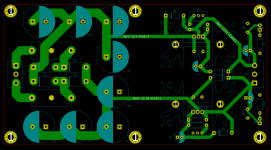
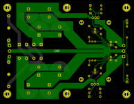
I have attached the PCB layout (note that the size of the PCB and the screw holes were determined by my case). There is a solid ground plane.
As far as I understand you, the 240R resistor is at the right spot, right?
Very mysterious. Maybe my probing could be an issue? But I guess one cannot do a lot of things wrong with measuring the load regulation with a multimeter.
For the ripple measurement I use my scope with AC coupling, otherwise I get a lot of noise due to the loop area of the ground connection of the probe.
First check has to be that the input voltage including ripple when under load is always above the minimum required for regulation. That means you need 3 or 4 volts headroom at least.
I guess you forget to take into account an input (rectified) voltage.
With the 10R resistor, the voltage at the input of the regulator is about 19V, so there is enough headroom to the 12V.
Your R3 and R4 connections to pin 2 are ideally right at the regulator body- not down near the output connector.
Physical layout and how things connect is important. The 240 ohm should connect directly to the regulator pin and not at some place further down the line, be that PCB print or wire.
I have attached the PCB layout (note that the size of the PCB and the screw holes were determined by my case). There is a solid ground plane.
As far as I understand you, the 240R resistor is at the right spot, right?
What do you mean exactly? I thought that the placement of that cap is not as critical, since it should only improve the ripple rejection according to the datasheet.Similarly, for both rails, the connection of RV +its 10uF bypass cap to 0v should as close as possible to the output connector 0v - not on the shared impedance between it and teh reservoir caps, and definitely not at the 0v junction of all the reservoir capacitors.
Very mysterious. Maybe my probing could be an issue? But I guess one cannot do a lot of things wrong with measuring the load regulation with a multimeter.
For the ripple measurement I use my scope with AC coupling, otherwise I get a lot of noise due to the loop area of the ground connection of the probe.
Those PCB traces are probably very thin looking when seen for real.
As a quick test you could add your 10 ohm load to the output terminals of the board (so you get your 11.6 volts across the load) and then measure the volt drop from between each output terminal back to the regulator. See what is dropped along the print.
As a quick test you could add your 10 ohm load to the output terminals of the board (so you get your 11.6 volts across the load) and then measure the volt drop from between each output terminal back to the regulator. See what is dropped along the print.
At first sight, it is ok. Unless a sense ground connection is made to the plane, but not to the exact output contact (but I'm not sure it can give a 0.4V error with the only 1A DC).here the PCB
(They say in the datasheet: "In order to optimize the load regulation, the current set resistor R1 (240R, see Figure 6. Basic adjustable regulator) should be tied as close as possible to the regulator, while the ground terminal of R2 should be near the ground of the load to provide remote ground sensing." (ST)
Or from ONsemi: "Load Regulation. The LM317 is capable of providing extremely good load regulation, but a few precautions are needed to obtain maximum performance. For best performance, the programming resistor (R1, 240R) should be connected as close to the regulator as possible to minimize line drops which effectively appear in series with the reference, thereby degrading regulation. The ground end of R2 can be returned near the load ground to provide remote ground sensing and improve load regulation.
- your design is close to this requirement, except for a ground plane connection).
Last edited:
Those PCB traces are probably very thin looking when seen for real.
As a quick test you could add your 10 ohm load to the output terminals of the board (so you get your 11.6 volts across the load) and then measure the volt drop from between each output terminal back to the regulator. See what is dropped along the print.
First mystery solved. Thanks to your suggestion I checked the voltage at the regulator, it was very stable. With that knowledge I found out that this one particular alligator clamp cable I was using to connect the load to had a resistance of nearly half an ohm. Since I was probing with the multi-meter at the load, I got this voltage drop....
Now only the ripple remains questionable to me. 80db ripple rejection should mean a reduction by a factor of 10^(80/20) = 1e4, correct? But I only see a factor of about 10. Even for the 60db it should be 1000.
Maybe my probing is the culprit again?
Do you know any reference oscilloscope plots of an LM317 I could compare my measurements against?
I guess I will test the CC-R-CC capacitance multiplier on a breadboard as suggested by martin clark.
 that's good.
As to ripple rejection and so on... now that really does come down to physical layout and PCB resistances. The ripple rejection has to be measured using that same 240 ohm resistor connection point because that is the absolute reference point for the chip.
It is exactly the same kind of issues we have when dealing with hum and noise in amplifiers and having too attend to grounding layouts.
Measuring low voltage ripple and noise can be hard. Coaxial measurement is needed, with very short ground leads (a few mm). Or use probe tip and short ground spring.
LT instruction about probing technique (Appendix C): https://www.analog.com/media/en/technical-documentation/application-notes/an101f.pdf
LT instruction about probing technique (Appendix C): https://www.analog.com/media/en/technical-documentation/application-notes/an101f.pdf
Using a standard ground plane* as a ground return is probably the worst thing you can do for your regulator's PSRR. I suppose this is the reason for such high ripple measured on the output.
I see you use KiCAD for PCB designing - if you upload the project I can try to explain what I have in mind by fixing its topology.
*standard ground plane - the one which just utilizes the whole PCB area without any cutouts.
I see you use KiCAD for PCB designing - if you upload the project I can try to explain what I have in mind by fixing its topology.
*standard ground plane - the one which just utilizes the whole PCB area without any cutouts.
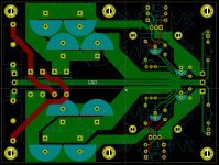
the regulators use only a few mA ground current, but in your layout the return current (1.5A) in the ground plane flows all the way from the right side of your circuit board to the reservoir caps and not only that, it tries to flow exactly below where the supply current flows, just below the 337 where several gnd connections are. The magnetic field is the reason.
if you move the gnd output close to your big caps and make a groove in the plane to prevent this.
Another issue will be the RF (3MHz) created by the rectifier diodes, better get 5A Schottky.
For your current need only a single 3300uF is sufficient
if you move the gnd output close to your big caps and make a groove in the plane to prevent this.
Another issue will be the RF (3MHz) created by the rectifier diodes, better get 5A Schottky.
For your current need only a single 3300uF is sufficient
You connected a load between the (+) output to the positive rail? The (+) LM317 regulators do not sink current. Loads must be connected between the (+) output and ground. That way, the regulator can source current, which is what a series type (+) regulator does. Then you will get the good regulation a properly applied LM317 can supply. Same goes with the LM337, with all polarities reversed, of course.
I have attached the KiCAD project.
Ahh, and another investigation: If I connect a load between the output of the LM337 and ground and measure the ripple at the output of the LM317, I get around 40 mV-pp. Further, when I connect a load to both rails to ground, the ripple at 1.2A load decreases to 20mV-pp. Still much more than I hoped to achieve, but much smaller than if I remove one load.
How can this be explained? The LEDs should draw more than 5 mA.
Using a standard ground plane* as a ground return is probably the worst thing you can do for your regulator's PSRR. I suppose this is the reason for such high ripple measured on the output.
I see you use KiCAD for PCB designing - if you upload the project I can try to explain what I have in mind by fixing its topology.
*standard ground plane - the one which just utilizes the whole PCB area without any cutouts.
That sounds bad. Is there a way to test whether this is the case? I tried to connect the ground of the load to the left side of the PCB, did not make a difference.the regulators use only a few mA ground current, but in your layout the return current (1.5A) in the ground plane flows all the way from the right side of your circuit board to the reservoir caps and not only that, it tries to flow exactly below where the supply current flows, just below the 337 where several gnd connections are. The magnetic field is the reason.
if you move the gnd output close to your big caps and make a groove in the plane to prevent this.
Any recommended part?Another issue will be the RF (3MHz) created by the rectifier diodes, better get 5A Schottky.
I have seen many designs which use even more capacitance or capacitance multipliers?For your current need only a single 3300uF is sufficient
what do you mean with (+) output and positive rail?You connected a load between the (+) output to the positive rail? The (+) LM317 regulators do not sink current. Loads must be connected between the (+) output and ground. That way, the regulator can source current, which is what a series type (+) regulator does. Then you will get the good regulation a properly applied LM317 can supply. Same goes with the LM337, with all polarities reversed, of course.
Ahh, and another investigation: If I connect a load between the output of the LM337 and ground and measure the ripple at the output of the LM317, I get around 40 mV-pp. Further, when I connect a load to both rails to ground, the ripple at 1.2A load decreases to 20mV-pp. Still much more than I hoped to achieve, but much smaller than if I remove one load.
How can this be explained? The LEDs should draw more than 5 mA.
Attachments
Last edited:
One suggestion - the example PCB layout you give of the multiple reservoir capacitors does not exploit them, at all.
Especially on the -ve rail side your PCB image illustrates: you have the rectified voltage connected to the terminal of one 3300uF capacitor, which also directly feeds the LM337. The other reservoir capacitors are tacked-on to this same connection - yes, they are in parallel, but each has a trace to it off the one noisy connection - they are at the far end of a side branch - and very much less-effective than they could be!
If instead the chain of reservoir caps was fed from the rectifier at one end, and the smoothed voltage output taken to the regulator from the other- exactly like your schematic - the -ve supply would perform better; the impedance of all those trace would work in your favour.
All the comments above from the contributors to this thread essentially amount to the same thing: Look critically at the difference between the 1. schematic you posted, and 2. the PCB layout you have.
The impedance of every trace matters.
Last edited:
Thanks for all your suggestions!
I tried to use an other transformer, a classical one (no toroid) and without center tap. This means I could only get half bridge rectification. Strangely enough, the ripple was much lower.
This got me thinking about the differences between the two setups. With my toroid transformer, I have connected the center tap to mains earth. If I remove this connection, then the ripple drops down to 2.6-3.2 mV-pp at 1.2A. Although I would actually not call this ripple but rather noise.
Is this a probing issue (since the oscilloscope ground is also connected to mains earth and hence forms a big ground loop) or something else?
I thought that this does not matter at these frequencies, but I might be wrong. I see a slightly larger noise of 3.2 mV-pp at the negative rail compared to 2.6mV-pp at the positive rail.One suggestion - the example PCB layout you give of the multiple reservoir capacitors does not exploit them, at all.
Especially on the -ve rail side your PCB image illustrates: you have the rectified voltage connected to the terminal of one 3300uF capacitor, which also directly feeds the LM337. The other reservoir capacitors are tacked-on to this same connection - yes, they are in parallel, but each has a trace to it off the one noisy connection - they are at the far end of a side branch - and very much less-effective than they could be!
If instead the chain of reservoir caps was fed from the rectifier at one end, and the smoothed voltage output taken to the regulator from the other- exactly like your schematic - the -ve supply would perform better; the impedance of all those trace would work in your favour.
All the comments above from the contributors to this thread essentially amount to the same thing: Look critically at the difference between the 1. schematic you posted, and 2. the PCB layout you have.
The impedance of every trace matters.
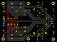
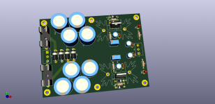
I'm attaching here the board with changes and some pictures.
Of course the board can be improved even more.
Of course the board can be improved even more.
Attachments
- Home
- Amplifiers
- Power Supplies
- LM317/337 load regulation and ripple