Since this is only about having fun, let's check out another unity-gain buffer.
The LM1875 chipamp is beloved by many, but it is not unity gain stable.
However, there is a circuit in the datasheet of its twin brother, LM675, titled "Non-Inverting Unity Gain Operation".
See Fig. 12 of :
https://www.ti.com/lit/ds/symlink/lm675.pdf
Now the beauty of this is that :
1) You can use whatever rail voltage you have directly, up to +/-30V.
2) Output offset voltage is ~1mV, so no need for output coupling caps.
3) It will drive any load down to a few ohms with ease.
🙂
Patrick
PS I have not tested myself.
So build at own risk.
But it is a very low-cost experiment.
😉
Patrick
So build at own risk.
But it is a very low-cost experiment.
😉
Patrick
I see pictures when some bypass the IPS with a wire,any one done that and can comment on the sound?
> Or one can simply use LM675 as a power amp and remove the rest of the circuit?
Yes, but that wouldn't be fun. 😉
Patrick
Yes, but that wouldn't be fun. 😉
Patrick
... bypass the IPS with a wire,any one done that and can comment on the sound?
Nelson Pass himself did that and discussed it briefly, over in the other thread, the one named Official M2 Schematic. Don't remember how long ago he posted, sorry.
> Or one can simply use LM675 as a power amp and remove the rest of the circuit?
Yes, but that wouldn't be fun. 😉
Patrick
It is interesting at the extreme. I am into extremes. How do you calculate the r1,r2 and c? from that LM674 datasheet schematic? Seems it can be anything lower than a 1/10 ratio.
I also would be interested in your buffer with fet and tta004Bs you posted a while back. I forget how much PS voltage it can take but I would need it to be able to take +/-30 to be safe at turn on and such. If you are willing to provide a complete schematic with PS. I am willing to try to make PCB for it and try it out. 🙂
> How do you calculate the r1,r2 and c? from that LM675 datasheet schematic?
Just use the values in the LM675 datasheet.
Here is the proof that LM1875 is essentially the same :
https://e2e.ti.com/support/audio/f/audio-forum/571418/lm675-vs-lm1875-what-s-the-difference
> I also would be interested in your buffer with fet and tta004Bs you posted a while back.
> I forget how much PS voltage it can take but I would need it to be able to take +/-30 to be safe at turn on and such.
The 2SK117/209 can take 50V. The TTA004 even more.
But I do not like running the 209 at anywhere > 50mW.
So I only recommend +/-12V.
But if you can get 2SK117GR, then +/-30V rails are no issue.
> If you are willing to provide a complete schematic with PS.
To come in a while.
> I am willing to try to make PCB for it and try it out.
Someone has already gotten PCBs made from my Gerbers.
You can contact me by PM, and I'll tell you who to contact for PCBs, etc.
Patrick
Another extreme project might be to strip out and delete all of the supply voltage protection folderol from the Tucson daughter card, then install a 140 volt opamp like the LTC6090 [datasheet attached below]. Be sure to buy the LTC6090 device which is guaranteed unity gain stable, i.e., the one WITHOUT the dash-5 suffix. Since Tucson connects the opamp in unity gain circuit topology. Now the daughter card can handle plus and minus 70 volt supplies.
_
_
Attachments
> Now the daughter card can handle plus and minus 70 volt supplies.
A normal line input is 2Vrms ?
The transformer is 1:5.
So max Vout is +/-17V.
Why would one need +/-70V rails ?
Just for fun ?
😉
Patrick
A normal line input is 2Vrms ?
The transformer is 1:5.
So max Vout is +/-17V.
Why would one need +/-70V rails ?
Just for fun ?
😉
Patrick
Another extreme project might be to strip out and delete all of the supply voltage protection folderol from the Tucson daughter card, then install a 140 volt opamp like the LTC6090 [datasheet attached below]. Be sure to buy the LTC6090 device which is guaranteed unity gain stable, i.e., the one WITHOUT the dash-5 suffix. Since Tucson connects the opamp in unity gain circuit topology. Now the daughter card can handle plus and minus 70 volt supplies.
_
I have a dozen or so BB 3584JM too. 😉
> How do you calculate the r1,r2 and c? from that LM675 datasheet schematic?
Just use the values in the LM675 datasheet.
no value is given there
that in fig 3 is for a split supply from std supply. How does that apply to the unity gain buffer in fig 12??
Maybe whatever Mark used for the IPS8 seems close?
RS 100 R1 221 and R2 2k and 4.7n for the C
RS 100 R1 221 and R2 2k and 4.7n for the C
I've copied a snippet from page 10 of the M2 user manual, found on the First Watt website (here)
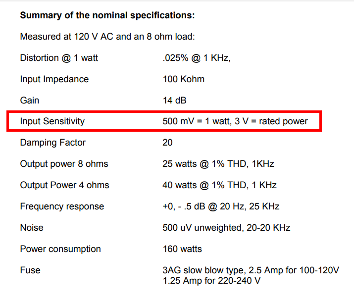
The M2 amp has three stages: a (JFET) source follower, an Edcor transformer, and a (power MOSFET) source follower. You can calculate its gain after you're told that 0.5V RMS at the input, produces 2.828V RMS at the output [n.b. 2.828V RMS delivers exactly 1 watt into 8 ohms]. Since the gain of each source follower stage is unity or just a smidgen less, you've effectively calculated the gain of the Edcor transformer. However, the numerical value of gain is not equal to SQRT(15000 ohms / 600 ohms), is it? That's weird and wacky and fun.
Foaming at the mouth extremists, who use enormous heatsinks on their homebuilt M2x's, might conceivably run one at 4X the power dissipation (2X the supply voltage and 2X the bias current) so they will need an input signal 2X bigger than the First Watt M2 needs. They'd need 6V RMS. Since they're extremists, round up to 10V RMS for a healthy margin of safety / wretched excess. Fortunately there exist preamplifiers which are able to swing their outputs 10V RMS, so this is not a show stopper. In fact I think Douglas Self likes to mention that his latest DIY preamp design using NE5532s on 34V of supply rail (plus/minus 17V), will deliver 10V RMS.
These extremists need M2X input stages that won't self destruct when connected to power supplies 2X larger than the First Watt M2 uses. There are several ways to make input cards tolerate high supply voltages; Tucson illustrates one of them, IPS7 illustrates a second, IPS8 illustrates a third, and there exist still more possibilities that work well. Choose the one which sings to you. If you're an extremist, perhaps the LTC6090 might be it.
_
Attachments

Last edited:
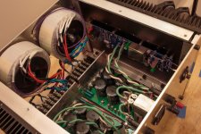
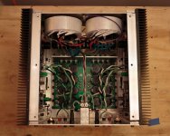
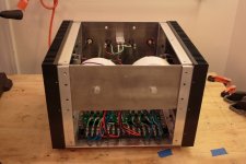
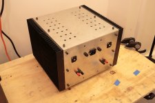
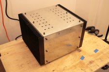
My M2X
Here's my M2X in a chassis I built around some surplus heatsinks I found online. The PSU boards are my own design - I prefer screw terminals, and I needed a longer aspect ratio to fit into this chassis. I also wanted extra terminals before and after the pi resistors for attaching a CapMX if I wanted to substitute one for the pi resistors (for a future design).
I am running 0.39R source resistors to up the bias a bit, because I have more than enough heatsink for it. Internal air temp is 110 deg. F / 43 deg. C. The heatsinks themselves are warm, but I can leave my hands on them indefinitely without any discomfort.
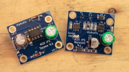
I built up the Tucson first to get it playing, and then I soldered up the Norwood for fun this afternoon - first time to use SMD.
Here's my M2X in a chassis I built around some surplus heatsinks I found online. The PSU boards are my own design - I prefer screw terminals, and I needed a longer aspect ratio to fit into this chassis. I also wanted extra terminals before and after the pi resistors for attaching a CapMX if I wanted to substitute one for the pi resistors (for a future design).
I am running 0.39R source resistors to up the bias a bit, because I have more than enough heatsink for it. Internal air temp is 110 deg. F / 43 deg. C. The heatsinks themselves are warm, but I can leave my hands on them indefinitely without any discomfort.
I built up the Tucson first to get it playing, and then I soldered up the Norwood for fun this afternoon - first time to use SMD.
Attachments

- Home
- Amplifiers
- Pass Labs
- The diyAudio First Watt M2x