Merlin, too bad our first encounter is because of this. I wanna thank you for your website and both books. They have helped me tremendously. Especially the guitar preamp book is a one stop shop for the guitar amp builder.
Somehow I have more trouble entering the hifi world, hence this (and other) threads.
I mentioned Merlin's grounding pdf in the first post, but people keep reminding me of that pdf. I don't mind, it deserves it.
It's not my first amp (3rd), but as stated before, the hifi world is something else. Maybe it's me, maybe my background or lack thereof. Anyhow, here's my pride and joy:
Could you tell us what the real cause is?
KOC mentions this in one of his tech books, by installing an A/C ground lift.
I take it a few steps further.
a. I do not connect the A/C neutral wire to the chasses.
b. I do install a couple of A/C chokes on L1 and Return, and a couple of 0.1 mF chip caps from L1 and L2 to A/C neutral.
c. Then, you can use any part of the chassis as ground or (return ), and not have to jump through all those hoops with regards to single-point-ground.
-g
OMG what a brutal and dangerous post. You are actually calling AC ground the neutral. There are 3 wires, hot, neutral, and ground. Words matter. Yours are so wrong they can be dangerous.
OMG what a brutal and dangerous post. You are actually calling AC ground the neutral. There are 3 wires, hot, neutral, and ground. Words matter. Yours are so wrong they can be dangerous.
fine. go talk to KOC about it. you probably know who he is.....he much more , how should I say, more educated and professional about it, than Lounge Lizard is..........
YES. Please don't do any of the things in post #42. Very dangerous and criminally wrong.
God.... take a pill......
https://www.te.com/usa-en/product-CAT-C8114-EJ79.html?r=3&compatible=2-6609006-1
Chris imho it's best to ignore, and not feed, and use the report button when flagrantly dangerous information is presented.
Chris imho it's best to ignore, and not feed, and use the report button when flagrantly dangerous information is presented.
My experience is the opposite, reporting a post gets an inconsistent response, so calling it out is the safest thing to do.
not what I said.OMG what a brutal and dangerous post. You are actually calling AC ground the neutral. There are 3 wires, hot, neutral, and ground. Words matter. Yours are so wrong they can be dangerous.
I said I do not connect the A/C ground wire to the chassis.
I could post a wiring diagram, but if others want to run with an A/C ground lift, no skin off my nose.... I was just answering the question..... or run with a bunch of hum in the loud speaker, I don't care........... if using A/C filtering on the input of the power transformer is such a sin, fine, don't filter the A/C power coming in........ as it is apparently a criminal act to do so....... wonder if you are a cronies working for lounge lizard . . . .
Well, those of us that can read can see that you wrote it. Also using caps that are not X or Y rated across the mains is very dangerous. Your post is dangerous in multiple ways.
Well, those of us that can read can see that you wrote it. Also using caps that are not X or Y rated across the mains is very dangerous. Your post is dangerous in multiple ways.
any time you work with A/C mains on the primary side, or D/C mains on the secondary side, one better had be a trained professional ; such as I ; to do this kind of scratch build kind of work.....
.... the main's switch I used last time, those parts are embedded into the switch..... very, very common electrical part....... besides, I see so many threads on filtering on the secondary side, but nothing on the primary side.......
It might help the OP to think of your stereo gnd as a Y shaped gnd bus. Both L & R OP stages go to the bottom end of the two sticky up bits of the Y, phase splitters next, then IP stages at the top,the leg of the Y goes to your PSU smoothing cap, IE the base of a star gnd.
Any IP sockets from outside should be connected gnd wise by a thin wire to star gnd, then using screened cable, from each IP, screen to the socket gnd, + to socket inner run the screened cable to your IP valve but cut the screen off at this end, Pop a bit of heatshrink tube over the end to keep things neat, all you have popping out is the inner + going to your grid.
See crude attachment, Andy.
Attachments

Unfortunately precision and accuracy is needed for safety. I'd get shot being imprecise between "certified quantum entropy" and "quantum certified entropy".
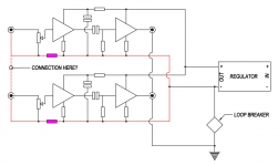
Looking at the hifisonics link posted earlier and the attached is based on what I saw there. The magenta resistors are 10 Ohm and intended to break the internal cross channel loop formed by connecting the grounds at the input. The connection between channels at the input is supposed to keep the loop formed by common channel ground at the source component out of the amplifier. I don’t understand the connection though. If the added resistors are sufficient to break the internal loop wouldn’t they break the external loop too?
Edit: Sorry cant get that diagram to turn the right way around
Edit: Sorry cant get that diagram to turn the right way around
Attachments
Last edited by a moderator:
I'm still have trouble applying that idea to my situation, with the PCB's as they are.
I've been (over)thinking for a long time now. I kinda started the practical stuff and see what I get...
I've been (over)thinking for a long time now. I kinda started the practical stuff and see what I get...
If "loop breaker" is the now-conventional double-diode-doubled safety ground loop breaker, the drawing's not correct. The output signal shields ("grounds") should be connected to signal "ground" rather than safety "ground".
Those 10R resistors could also be placed instead between the regulator's "- out" and each channel's signal "ground" buss. (The "connection here?" in either case happens at the far end of the incoming signal coax.) This would keep all of each channel's return currents in its own buss.
A further upgrade, that also costs nothing, is to use interconnecting cables with 2 inner conductors and a common shield. Both hot signal and return run inside the shield, which carries no signal. In your design, with signal "ground" floated from safety ground and chassis, the shield can be connected to chassis on both ends. Takes 3 connections per channel and doesn't matter much in normal home installations, but it's the ideal. And cheap.
Remember that coax, or balanced lines for that matter, get their external noise immunity from having equal and identical (opposite polarity) currents in both conductors. Two interconnecting cables with one of their conductors connected together at both ends will share those conductors equally. Half of the left channel signal return current flows in the right channel shield, and vice-versa, in the conventional case. Works for normal short runs in home settings, but not ideal. Just food for thought.
YOS,
Chris
Last edited:
- Home
- Amplifiers
- Tubes / Valves
- Yet another grounding thread