astouffer you mean that "Just have to settle on the wire gauges" and that should work the same way that inteleaved? , perhaps better.
I don't understand what this means. I am interested in your opinion.
In the past I considered winding transformers but never went past the design stage. Now I have all the parts except for the magnet wire. Still deciding on what gauges to use. My goal is a 100 watt push pull with a 3.3k primary and 8 ohm secondary.
I would check the phases on the primary windings.
Opening primary links
Primary-Secondary phase
astouffer, I checked the 3 primary windings applying 1KHz sinewave at the secondary and traced each winding for phase matching, and finally I reconnected them also in phase. That was originally OK. The N1/N2 ratio resulted as expected ~18:1

I will now play a little with euro21 proposal.
Try to measure the transformer as ordinary 1:19 stepup:
Generator (1V, 100Hz) -> 8R resistor - > secondary : primary -> 3k resistor
Results as expected:
Vin (1Vpp , 50 Hz) applied to secondary winding configured for 8 Ohm (two windings in parallel in series with 2 windings in parallel) , with 8R resistor load.
Vout ( 16 Vpp ) obtained from primary winding with 2K6 Ohms load resistor. This is a little less tan 18:1 N1/N2 probably because 50 Hz instead of 100 Hz.
Signals
Input
Output
Generator trafo
With this setup the frequency response 20~20 KHz is lousy 😡
I measured some static transformer parameters:
Lp = 11H primary inductance - open secondary
Ls = 41 mH secondary inductance - open primary
LL = 61 mH primary leakage inductance - shorted secondary
Rs = 0,63 Ohms secondary resistance
Rp = 117 Ohms primary resistance
Cp-s = 135 pF primary - secondary capacitance
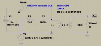
euro21, based upon these measured values I have changed some parameters of your simulation. I would like to implement this CCS but I can't get the FETs that are depletion mode, 400V and Rsdon = 25 Ohms.
How can make it with more standard components? This measurement setup is very interesting.
You are using a 450V sine signal applied to the transformer primary, but in my case this would be something between 177~200 VAC which is the value shown in the simulation and in the transformer calculation. Are you Ok with this value?
Also, can a lower voltage be used for the CCS ? (eg: 12VCC )
Attachments
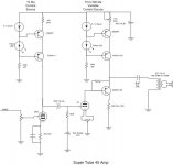
Try BJT CCS as in the attached schematic.
If the CCS has enough isolation (enough large impedance at given AC frequency), lower DC is enough, but it must be enough large for CCS plus Iccs*DCR of primary.
OK, thank you. And again:
"You are using a 450V sine signal applied to the transformer primary, but in my case this would be something between 177~200 VAC which is the value shown in the simulation and in the transformer calculation. Are you Ok with this value?"
In my example the 450V peek voltage generates -almost- full current swing (0-140mA) within the primary, so better represents the full driving of (70mA static anode current) tube.
Of course, any size of AC excitation can be used.
Of course, any size of AC excitation can be used.
- Home
- Amplifiers
- Tubes / Valves
- 300B SE amp - need help with output transformer problem