Hello everybody, with reference to tubes, I am a 67 years old newbie, although I am an experienced digital and microsystems design engineer.
Along with a good friend we decided to build a SE stereo audio amplifier. He is the owner of several pieces of excellent famous brands class A amplifiers, meaning that he knows how they sound. I honestly prefer solid state devices, but, as we are taking all this as a hobby, learning and having fun is the main point here.
So take this as a sincere apology to those experts that this forum is full of, begging for your mercy and patience, which I respect, in my consulting.
When I was almost a child I built some push pull tube audio amps but always following some trusted schematic. I was lucky and enjoyed the ride.
In this case, and many years after, we started by buying these 4 books from Amazon:
Book #1
Book #2
Book #3
Book #4
This was interesting reading but to be honest I found some errors in the amplifier schematic and also typos. I made my own simulation of the circuit using LTspice, and send it to the author, who was very kind to reply and also approve my proposed changes and corrections, most of them because some component values explained in the provided videos, differed with those in the printed text of the books. Grid polarization values and confusing data about number of turns in the output transformer, resistor values in the power supply, etc.
Once I had all these more or less clear, I focused on building the power supply transformer, filter chokes and finally the output transformer. I have access to a friend's professional winding machines, so we built the power transformer and chokes in just one evening. Measured chokes' inductances, they matched those of the calculations.
I found the output transformer procedure quite straightforward and I collected all the calculation in an Excel spreadsheet, that worked fine.
Here are some pictures of transformers and chokes:
Power transformer
Choke view #1
Choke view #2
Output transformer view #1
Output transformer view #2
Output transformer view #3
Output transformer view #4
Pi bobbin
Power supply
Wooden 300B amplifier
I will not reproduce any original images from the books, if somebody is interested it should honor the author by purchasing the books. But I can offer a printout of my own LTspice simulation, that involves some intellectual dedication in putting the pieces together with tube models, some hours working over the circuit errors and specially the output transformer model. The rest of the circuit is pretty conventional, there is nothing new about it. Even more, I deleted the NFB loop that was taken not from the output transformer secondary winding but from near the 300B grid. As I said before, some values shown are not the original ones and I have made corrections. The complete circuit is up and running assembled over a piece of wood and the obtained voltages and signals seem to be normal. They perfectly match the simulation.
Simulation corrected schematic
Speaker output waveform
Simulated frequency and phase response
So then, what's the problem Bob? 😕
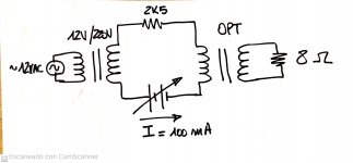
Once the output transformer is connected and loaded with an 8 Ohm resistor, the output is only 500 mV. The amplitude measured at the 300B plate falls from a nice large 200 Vpp swing to a poor 37 Vpp. Changing the output resistor value or reconfiguring the secondary taps and windings, the voltage raises. The best I could get was a 7 Vpp signal, with a relatively good frequency response.
Perhaps I made a mistake here - sorry guys for this:
Changing the original spec from a regular multiple layer transformer to a PI winding transformer. If you take a look at the output transformer pictures, I designed and fabricated with my 3D printer, a non standard bobbin former to accomodate 7 PI parallel vertical windings; 3 of them for the primary and 4 for the secondary. This hand made custom transformer complies with the original M4 GOSS lamination size, number of turns and gap specification as shown in the transformer book.
When taken out from the circuit and measured with an LCR meter, the values seem to be normal. 12H for the primary and 116 Ohms resistance. The instrument also shows the calculated impedance that reads around 3K Ohms. Primary and secondary resistance values are also normal and as expected.
But all this measurements are not "in circuit" and there is no DC component at the primary, that should be between 60mA to 100mA.
All the signals from the input up to the 300B grid are nice and perfectly normal. So all the suspicions point to this "innovative" transformer winding probably shorting the plate voltage swing. Perhaps because there may be some special considerations when using PI winding, that in theory should be the best way to get a balanced transformer in terms of equal size windings and improved frquency response.
Secondary windings possible configurations
Before I build another brand new output transformer, I would like to hear some authorized opinion from the experts. Any ideas and help will be, as always, very much appreciated.
Along with a good friend we decided to build a SE stereo audio amplifier. He is the owner of several pieces of excellent famous brands class A amplifiers, meaning that he knows how they sound. I honestly prefer solid state devices, but, as we are taking all this as a hobby, learning and having fun is the main point here.
So take this as a sincere apology to those experts that this forum is full of, begging for your mercy and patience, which I respect, in my consulting.
When I was almost a child I built some push pull tube audio amps but always following some trusted schematic. I was lucky and enjoyed the ride.
In this case, and many years after, we started by buying these 4 books from Amazon:
Book #1
Book #2
Book #3
Book #4
This was interesting reading but to be honest I found some errors in the amplifier schematic and also typos. I made my own simulation of the circuit using LTspice, and send it to the author, who was very kind to reply and also approve my proposed changes and corrections, most of them because some component values explained in the provided videos, differed with those in the printed text of the books. Grid polarization values and confusing data about number of turns in the output transformer, resistor values in the power supply, etc.
Once I had all these more or less clear, I focused on building the power supply transformer, filter chokes and finally the output transformer. I have access to a friend's professional winding machines, so we built the power transformer and chokes in just one evening. Measured chokes' inductances, they matched those of the calculations.
I found the output transformer procedure quite straightforward and I collected all the calculation in an Excel spreadsheet, that worked fine.
Here are some pictures of transformers and chokes:
Power transformer
Choke view #1
Choke view #2
Output transformer view #1
Output transformer view #2
Output transformer view #3
Output transformer view #4
Pi bobbin
Power supply
Wooden 300B amplifier
I will not reproduce any original images from the books, if somebody is interested it should honor the author by purchasing the books. But I can offer a printout of my own LTspice simulation, that involves some intellectual dedication in putting the pieces together with tube models, some hours working over the circuit errors and specially the output transformer model. The rest of the circuit is pretty conventional, there is nothing new about it. Even more, I deleted the NFB loop that was taken not from the output transformer secondary winding but from near the 300B grid. As I said before, some values shown are not the original ones and I have made corrections. The complete circuit is up and running assembled over a piece of wood and the obtained voltages and signals seem to be normal. They perfectly match the simulation.
Simulation corrected schematic
Speaker output waveform
Simulated frequency and phase response
So then, what's the problem Bob? 😕
Once the output transformer is connected and loaded with an 8 Ohm resistor, the output is only 500 mV. The amplitude measured at the 300B plate falls from a nice large 200 Vpp swing to a poor 37 Vpp. Changing the output resistor value or reconfiguring the secondary taps and windings, the voltage raises. The best I could get was a 7 Vpp signal, with a relatively good frequency response.
Perhaps I made a mistake here - sorry guys for this:
Changing the original spec from a regular multiple layer transformer to a PI winding transformer. If you take a look at the output transformer pictures, I designed and fabricated with my 3D printer, a non standard bobbin former to accomodate 7 PI parallel vertical windings; 3 of them for the primary and 4 for the secondary. This hand made custom transformer complies with the original M4 GOSS lamination size, number of turns and gap specification as shown in the transformer book.
When taken out from the circuit and measured with an LCR meter, the values seem to be normal. 12H for the primary and 116 Ohms resistance. The instrument also shows the calculated impedance that reads around 3K Ohms. Primary and secondary resistance values are also normal and as expected.
But all this measurements are not "in circuit" and there is no DC component at the primary, that should be between 60mA to 100mA.
All the signals from the input up to the 300B grid are nice and perfectly normal. So all the suspicions point to this "innovative" transformer winding probably shorting the plate voltage swing. Perhaps because there may be some special considerations when using PI winding, that in theory should be the best way to get a balanced transformer in terms of equal size windings and improved frquency response.
Secondary windings possible configurations
Before I build another brand new output transformer, I would like to hear some authorized opinion from the experts. Any ideas and help will be, as always, very much appreciated.
Try to measure the transformer as ordinary 1:19 stepup:
Generator (1V, 100Hz) -> 8R resistor - > secondary : primary -> 3k resistor
Generator (1V, 100Hz) -> 8R resistor - > secondary : primary -> 3k resistor
Thank you euro21, measurements using a signal generator reflect the correct primary / secondary turns ratio. All the windings had been checked OK. The output signal is good. Both your proposal and my measurement do not involve DC current, so they are of little help. They just show a good AC transformer behaviour with 18:1 N1/N2 ratio.
Hi
the method to check the trafo driving from secondary was expalined in this thread by me
OPT Characterization
In few time I will open other thread with another way more explained regarding the full test.
In the real world, not simulation
Walter
the method to check the trafo driving from secondary was expalined in this thread by me
OPT Characterization
In few time I will open other thread with another way more explained regarding the full test.
In the real world, not simulation
Walter
Hi
the method to check the trafo driving from secondary was expalined in this thread
OPT Characterization
In few time Iwill open other thread with another way more explained regaridng the full test.
In the real world, not simulation
Walter
the method to check the trafo driving from secondary was expalined in this thread
OPT Characterization
In few time Iwill open other thread with another way more explained regaridng the full test.
In the real world, not simulation
Walter
I would check the phases on the primary windings.
Good point ! I will do that and report. Thank you.
Hi
the method to check the trafo driving from secondary was expalined in this thread
OPT Characterization
In few time Iwill open other thread with another way more explained regaridng the full test.
In the real world, not simulation
Walter
Walter, as I said before, I am sure that I don't have enough level to follow the details, but the fact of no DC in your test circuit and measurements is worrying me, specially because this particular point has introduced enough wakefulness of lots of designers.
"There isn't the bias current because we haven't measured significative difference with it. "
I still believe that DC current overimposed on AC in any inductor produces an important change in inductance (to my knowledge), eg: the old Hanna's method as can be seen in the Radiotron Designer's Handbook - 4th Edition (1952) - pages 247~248
"Design with DC flux: When a DC flux is set up in the core by unbalanced direct currents in the windings the effective permeability is decreased, as is shown in the curves ... The amount of DC flux setup in the core depends on the DC magnetizing force (i.e. the total unbalanced ampere-turns in the windings), on the length of the magnetic circuit, an on the length of any air gap in the magnetic circuit. The effective permeability depends on: 1. the DC flux density in the core - 2. the AC flux density in the core - 3. the length of the air gap in the magnetic circuit"
So, please excuse my ignorance, could you please tell me in what could this method help in my case, to determine exactly what on my non working transformer.
I would like to ask you guys what do you think about the impact of PI winding in this case. I mean that I just built a transformer in this way keeping all the winding parameters that were thought for a standard multilayer winding transformer. Is this OK ?
I am preparing a test set with the possibility to check also the trafo with dc current.
It is not so easy to build but but no complicated.
In every case the test driving the trafo from secondary is the best way to check the performances.
Without dc current you can imagine the results with dc reading mainly the thd vs frequency.
This test explain you the how much is good your trafo.
Normally when you see a curve like a narrow U it is easy that the performances on bass (mainly) and high frequencies are not very good; with the dc current the part of the U became more vertical with thd increasing.
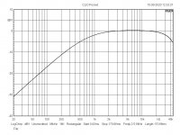
In attach, as for info, you can see a freq. response of a very good s.e. without nucleus; the response is linear from 2 kHz because from this frequency the coupling is mainly capacitive. Really it start before but for our purpose we say that 2 kHz are at at the same level of 1 kHz whit nucleus
In the other graph you can see the thd vs frquency of a s.e., high level, at 60 volt rms on 750 ohm ( like a Z of 300B), 5 watt at 8 ohms, no bias current.
The results it is very fine, with dc curren the thd will increas a bit from 20 to 200 hz (less or more)
As you see the shape is not a narrow U
Walter
It is not so easy to build but but no complicated.
In every case the test driving the trafo from secondary is the best way to check the performances.
Without dc current you can imagine the results with dc reading mainly the thd vs frequency.
This test explain you the how much is good your trafo.
Normally when you see a curve like a narrow U it is easy that the performances on bass (mainly) and high frequencies are not very good; with the dc current the part of the U became more vertical with thd increasing.
In attach, as for info, you can see a freq. response of a very good s.e. without nucleus; the response is linear from 2 kHz because from this frequency the coupling is mainly capacitive. Really it start before but for our purpose we say that 2 kHz are at at the same level of 1 kHz whit nucleus
In the other graph you can see the thd vs frquency of a s.e., high level, at 60 volt rms on 750 ohm ( like a Z of 300B), 5 watt at 8 ohms, no bias current.
The results it is very fine, with dc curren the thd will increas a bit from 20 to 200 hz (less or more)
As you see the shape is not a narrow U
Walter
Attachments
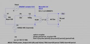
If the variable element is CCS, you must AC decouple it (CCS impedance is very high) with appropriate capacitor.
Another suggestion is this method:
I will try simulating, could you upload the .asc file please ?
What should I expect with my real transformer?
Thank you.
The simulation of inductance or trafos are limited and not real.
They say something but not all.
Walter
They say something but not all.
Walter
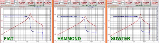
In attach the test on three different trafos
The software comes from our tech director of Audioreview, Fabrizio Montanucci, and it is for internal use.
You can see three different results for three different types but the shape of modulus until the resonance (inductive ) and after (capacitive) that are depending from different factors that are typical of each one and not possible to simulate.
Walter
Attachments
Last edited:
Voilá.I will try simulating, could you upload the .asc file please ?
Attachments
What is the opinion on pi winding compared to interleaved? I have the transformer winding bug again. 30 lbs of M6 laminations, some bobbins, and the winder is almost complete. Just have to settle on the wire gauges.
In attach the test on three different trafos
The software comes from our tech director of Audioreview, Fabrizio Montanucci, and it is for internal use.
You can see three different results for three different types but the shape of modulus until the resonance (inductive ) and after (capacitive) that are depending from different factors that are typical of each one and not possible to simulate.
Walter
Thank you very much Walter, I am sorry, I believe that all this information that you are providing was first shown here. I don't have enough skills to completely understand all this information. Besides this, a piece of software that I don't have handy, is needed. I'll better wait for you test set to come and see if is simple enough to give it a try.
Respectfully, let me point this out: at the moment I am not really worried about how good is my non working transformer unless I can make it work at least at a reasonable level once connected to the 300B. My problem is that I have a transformer that has been built "by the book", but clearly has a bug and doesn't work. All what I need is to find what is going on with this particular transformer.
I appreciate your effort. Also, I agree with you that normal simulations are not 100% real, but IMHO they help a lot if are well done. Thanks to simulation an my LTspice the amplifier is working from the electronic point of view.
astouffer you mean that "Just have to settle on the wire gauges" and that should work the same way that inteleaved? , perhaps better.What is the opinion on pi winding compared to interleaved? I have the transformer winding bug again. 30 lbs of M6 laminations, some bobbins, and the winder is almost complete. Just have to settle on the wire gauges.
I have the transformer winding bug again.
I don't understand what this means. I am interested in your opinion.
I would check the phases on the primary windings.
I am checking this tomorrow morning, I need to remove several pieces of Heat-shrink tubing. The primary has 3 windings 550 turns each that are connected with links, but it is easy to do. This could perfectly explain the problem or part of it. I will give you a report.
- Home
- Amplifiers
- Tubes / Valves
- 300B SE amp - need help with output transformer problem