Yes, I'm seeing that now that I'm looking at the circuit diagram. I'm only doing this for the positive rail, too much work to do for both.
If you don't feel like it don't do it at all. I'm not asking for this, it's pretty clear to me.
Do as you wish.
Do as you wish.
I measured without removing resistors and caps first, I got -18.6dBV between Cadj. and denoiser.
I will remove the resistors and connect different bridge now and see what we get with that.
I will remove the resistors and connect different bridge now and see what we get with that.
I posted the measurements I made for LM317N, LM317, LM338 and LT1084, all got somewhere between 28dB to 29dB PSRR reduction Cadj vs denoiser.
In order to allow continued exploration and sharing on the topics of noise floor measurements, measurement software selection, low noise preamplifier technology innovations, and REW software optimization, I have created a brand new discussion thread, just for those topics:
Measurement data and techniques for Elvee's De-Noizator: all implementations
Please continue discussions of De-Noizator (including VRDN's implementation of De-Noiser) measurements, lab techniques, data comparisons, and so forth, in that new thread. The present thread will remain focused only upon the VRDN PCB, its detailed parts list, construction tips, builder photos of completed units, parts sourcing issues, and so on.
Thanks and best wishes for very lively discussions with lots of insights and discoveries!
Will you update the design, or will you mention that the VRDN board does not offer the full denoiser performance in its current form?
I removed the CRC resistors and then applied power through a separate rectifier bridge to the resistor outputs and to the capacitor ground for the second set of capacitors. Everything performed on positive rail only.
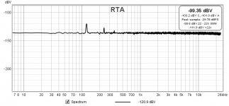
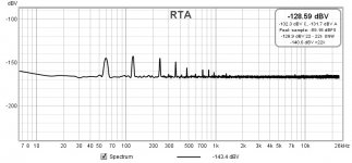
Positive rail input ripple with only capacitors before regulator

Positive rail output ripple with only caps before regulator denoiser disabled

Positive rail output ripple with only caps before regulator denoiser engaged

LM317 + Cadj. = PSRR@120Hz -83.9dBV
LM317 + Denoiser = PSRR@120Hz -106.4dBV
Looks like denoiser decreased PSRR -22.5dBV
Positive rail input ripple with only capacitors before regulator

Positive rail output ripple with only caps before regulator denoiser disabled

Positive rail output ripple with only caps before regulator denoiser engaged

LM317 + Cadj. = PSRR@120Hz -83.9dBV
LM317 + Denoiser = PSRR@120Hz -106.4dBV
Looks like denoiser decreased PSRR -22.5dBV
I removed the CRC resistors and then applied power through a separate rectifier bridge to the resistor outputs and to the capacitor ground for the second set of capacitors. Everything performed on positive rail only.
Positive rail input ripple with only capacitors before regulator
View attachment 925167
Positive rail output ripple with only caps before regulator denoiser disabled
View attachment 925168
Positive rail output ripple with only caps before regulator denoiser engaged
View attachment 925169
LM317 + Cadj. = PSRR@120Hz -83.9dBV
LM317 + Denoiser = PSRR@120Hz -106.4dBV
Looks like denoiser decreased PSRR -22.5dBV
How is the output ripple lower on your latest measurement than before?
Yeah I'm done with this board, removing input capacitance increases the performance of the regulator.
I just want to make it clear that I don't consider this board a good reference for a denoiser circuit. As in if you use this board you shouldn't judge the denoiser circuit on how a piece of audio gear "sounds" being powered by the VRDN.
I just want to make it clear that I don't consider this board a good reference for a denoiser circuit. As in if you use this board you shouldn't judge the denoiser circuit on how a piece of audio gear "sounds" being powered by the VRDN.
Good question, I will re-measure and post in the new thread.
I think it has to do with grounding. You don't use the bridge on the pcb so that might change some stuff. So basically just from design you could eliminate the 6600uF and have better performance.
Last edited:
Measurement data and techniques for Elvee's De-Noizator: all implementations
Please continue discussions of De-Noizator (including VRDN's implementation of De-Noiser) measurements, lab techniques, data comparisons, and so forth, in that new thread. The present thread will remain focused only upon the VRDN PCB, its detailed parts list, construction tips, builder photos of completed units, parts sourcing issues, and so on.
Thanks and best wishes for very lively discussions with lots of insights and discoveries!
@Mark Johnson
Seems clear what to do with TI LM337, can you confirm which BOM we need to use for On Semi?
Seems clear what to do with TI LM337, can you confirm which BOM we need to use for On Semi?
... board has an On Semi LM317 and a TI LM337, the comp network on both rails is the original 6.8nF +15 ohms.
The negative rail denoiser was not working after measuring it.
The positive rail was working perfectly.
I removed the ESR correction resistor on the negative rail output resistor and the negative rail is now working perfectly...
... to allow builders to use regulator chips from either TI or ON Semiconductor. If you've already built a couple of VRDNs using the Rev.A parts list and using ON Semiconductor chips, you don't need to change anything. However if you used the Rev.A parts list and TI voltage regulator chips, you need to make these changes: your board almost certainly will oscillate...
I am not aware of posted noise measurement for VDRN with On Semi on neg rail. Do you recommend builds with On Semi LM337 with BOM Rev A or Rev A2 to be sure of proper noise performance or it makes no measurable difference?... The second board has an On Semi LM317 and a TI LM337, the comp network on both rails is the original 6.8nF +15 ohms.
The negative rail denoiser was not working after measuring it.
The positive rail was working perfectly.
I removed the ESR correction resistor on the negative rail output resistor and the negative rail is now working perfectly...
Hi,
The Q2 512-BC32740TA is not available at the Mouser.
Could you please suggest replacement if possible.
Thanks.
The Q2 512-BC32740TA is not available at the Mouser.
Could you please suggest replacement if possible.
Thanks.
How about a shop "next door" to you 🙂
2580 in stock.
BC32740TA ON SEMICONDUCTOR - Transistor: PNP | bipolar; 45V; 0.8A; 625mW; TO92 | TME - Electronic components
Edit: ah, you are on the different location. Mouser has BC327-40 version with straight leads:
https://hr.mouser.com/ProductDetail...ld/BC32740BU/?qs=u3sZpSG73%2B4%2BlpJrwvvqyQ==
Last edited:
- Home
- Amplifiers
- Power Supplies
- VRDN: bipolar regulator PCB for line level ckts: ±11V to ±20V @ 1.5A with "De-Noiser"