I just took the voltages from the protection circuit in an NAD 2200, and I'm hoping for an extra set of eyes on a few numbers that I'm scratching my head over.
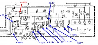
The one that's most concerning is the -45.5V I'm seeing where there's supposed to be -35V. Thoughts?
The one that's most concerning is the -45.5V I'm seeing where there's supposed to be -35V. Thoughts?
Attachments
hi Matt
I generally replace all the caps in the protection circuit. PW or HE Nichicon for the 47uf (C402/C401)and 22uf (C403), and Kemet film for the 0.47uf(C404) and 1uf (c401- it is marked as 0.47uf, but 1uf is generally what is fitted). The IC voltages all seem good, so replace C410.
Usually these low value caps are the problem
Do the relays click in?
Is protection on?
Have you replaced the relays?
Peter
Thanks for the suggestions Peter!
I pulled C410, and it checked out ok for capacitance, ESR, and leakage. But just to make sure, I put in a 1UF 100V Nichicon KL. Unfortunately, this had no effect on the -45.5V voltage reading. As for the other caps, I may end up replacing them as you suggest, but I'm hoping to pinpoint the exact cause of this issue first.
Protection is not on. These are the original relays. One only clicks in intermittently, and is visibly damaged from arcing. I plan to replace them after I get the circuit squared away.
also check M18 is -0.75v.
what are the are the voltage onQ403 and Q402?
I must confess I always start by replacing the relays first, as they can cause all sorts of issues.
what are the are the voltage onQ403 and Q402?
I must confess I always start by replacing the relays first, as they can cause all sorts of issues.
Do R418 and R419 measure correctly? Are they discoloured by heating at all?
Just checked, and both R418 and R419 measure spot on.
also check M18 is -0.75v.
what are the are the voltage onQ403 and Q402?
I must confess I always start by replacing the relays first, as they can cause all sorts of issues.
M18 is -0.75V. I measured Q403 and Q402 earlier, but need to circle back and recheck them to post the voltages.
Re replacing the relays first, I have been wondering if the one flaky relay could be what's causing this. . . .
D402 checks out ok in circuit.
Here's what I'm seeing for Q402 and Q403.
Q402
E +0.83
B +1.2
C +62.2
Q403
E 0
B -4.44
C +0.63
Here's what I'm seeing for Q402 and Q403.
Q402
E +0.83
B +1.2
C +62.2
Q403
E 0
B -4.44
C +0.63
The relay coils appear to be in series and so can not operate independently.
Your voltage reading of around 20 volts across R413 shows the relays must be energised as a current of around 40 milliamps is flowing. If that voltage is constant then the relays should be closed.
The -35/45 issue is open to interpretation. The diode is fed from a winding marked as 46 volts AC (so presumably rms) and that will give a DC voltage across the cap of 46*1.414 which is 65 volts but your DVM will probably not show anything like that because the voltage is just a half wave rectified pulse. The 0.47uF (shown incorrectly polarised on the diagram) can not provide much smoothing with R415/8 and 9 loading it.
That part of the circuit will be to provide a quick drop out when the AC line voltage is removed.
A scope would show the correct peak voltage on the cap, the DVM reading and its anyone's guess.
Thanks for the response and analysis!
Regarding whether my DVM will show the correct/real voltage at C410, I have another NAD 2200 here that I decided to check in the same spot. (This, too, has a single bad relay.) With this amp, I do actually read -35V at the cap.
So that got me wondering what, if any, differences there are component-wise between the two, at least in that part of the circuit.
Amp 1 (the one showing -45V):
C410: 1uF 100V (original)
Q403: RCA SK3245 (appears to be non-original)
Amp 2 (the one showing -35V):
C410: 0.47uF 100V (original)
Q403: 2SC2240 (original)
Otherwise the resistor values are the same. So not sure that anything there would really explain the -35V vs -45V discrepancy.
Fwiw, I also checked the voltages for Q402 and Q403 in Amp 2.
Q402
E +1.07
B +1.2
C +62.5
Q403
E 0
B -7.3
C +1.1
I dont think the 1uf or 0.47uf cap will make any difference.
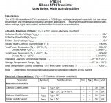
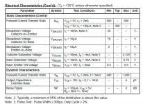
Typically the replacement for a 2SC2240 is a KSC1845, I do not know the other transistor, which could be the problem, perhaps (@mooly) could comment on the voltages
Typically the replacement for a 2SC2240 is a KSC1845, I do not know the other transistor, which could be the problem, perhaps (@mooly) could comment on the voltages
Actually, I mixed them up. It's Amp 2 that has the RCA SK3245, which is the amp showing the correct -35V. So that isn't the cause of the -45V in Amp 1.
EDITED:
Amp 1 (the one showing -45V):
C410: 1uF 100V (original)
Q403: 2SC2240 (original)
Amp 2 (the one showing -35V):
C410: 0.47uF 100V (original)
Q403: RCA SK3245 (appears to be non-original)
EDITED:
Amp 1 (the one showing -45V):
C410: 1uF 100V (original)
Q403: 2SC2240 (original)
Amp 2 (the one showing -35V):
C410: 0.47uF 100V (original)
Q403: RCA SK3245 (appears to be non-original)
If your volt meter has an AC voltage mode it might be instructive to measure the AC voltage before D402.
At the moment we've got two differing voltages at that -45.5V/-35V point. The smoothing is minimal and apparently designed so that the DC potential across C410 will collapse very quickly after mains power is removed. R419 is by far the biggest load placed after the diode designed, presumably, to collapse the DC across C410 very quickly.
Q403 should be off in normal operation. Is it just me or does it look like some current could be leaking through Q403 in the faulty amplifier?
With -45.5V in the faulty amp you'd expect the potential at the base of Q403 to be even lower than in the functioning one, yet it isn't. Something is pulling the potential more positive. Not only this but the collector voltage in the faulty amp is at 0.63V, only one diode drop above the emitter. The base is at -4V, relative to the emitter, so the transistor should be off.
In the good amp we've got -7V at the base, again it should be off, and in this case the collector is at 1.2V, so clearly not being pulled to ground through Q403.
Am I missing something? Analogue circuit analysis has never been my strong point. It looks like the relays are properly engaged in the faulty amp, yet it was said above that they click intermittently? They shouldn't click at all once the amp has turned on properly.
From what I can tell, in a working amplifier, Q403 does nothing except at shut down. No current, apart from any leakage, should flow through it in any direction. You should be able to safely remove it except you'll get turn off thump through the speakers once you do. If you remove Q403 and the voltages return to normal then that's the problem.
Anyone object to trying this?
Thanks for the response and analysis!
Regarding whether my DVM will show the correct/real voltage at C410, I have another NAD 2200 here that I decided to check in the same spot. (This, too, has a single bad relay.) With this amp, I do actually read -35V at the cap....
The only other thing I can see that could pull this voltage more positive (less negative) are Q337 and Q338 in the power amps. These each have the ability when turned on to apply +95 volts via a 180k and a common 150k onto the point you are measuring this voltage.
So a quick check of the collector voltage on both Q337 and 338 can done. Both should be off and probably at some negative voltage similar to what are measuring now (-45).
If not then confirm there is no voltage across either R317 and R318. If there is voltage across these then the related transistor is conducting when it shouldn't.
These transistors are in the overcurrent protection for the power amps.
Also compare the AC voltage on that secondary winding feeding D402 and confirm it is the same as on the other amp.
Some findings, none of which are particularly enlightening.
The secondary winding voltage going to D402 is 46VAC in both amps.
The collectors of Q337 and Q338 are showing -0.7V, both amps.
I can certainly try removing Q403, though it did test ok out of circuit.
EDIT: I pulled Q403--no change.
The secondary winding voltage going to D402 is 46VAC in both amps.
The collectors of Q337 and Q338 are showing -0.7V, both amps.
I can certainly try removing Q403, though it did test ok out of circuit.
EDIT: I pulled Q403--no change.
Last edited:
So at least we know the AC voltage feeding that point is the same in both amps.
I'd pull Q403 and see what happens to the voltages. Or you could swap Q403 from one amp to the other. See if the problem shifts with the transistor. At least then you'll confirm if that's causing the problem or not.
I'd pull Q403 and see what happens to the voltages. Or you could swap Q403 from one amp to the other. See if the problem shifts with the transistor. At least then you'll confirm if that's causing the problem or not.
Okay so the transistor isn't what's setting the voltages around it. If it's off then it shouldn't be.
You mentioned
Does this mean that the relays are switching when they shouldn't? Or did you mean they click after a few seconds upon power on, and click, almost immediately, after you remove power?
How does the switching of the relays compare from one amp to the other?
You mentioned
These are the original relays. One only clicks in intermittently,
Does this mean that the relays are switching when they shouldn't? Or did you mean they click after a few seconds upon power on, and click, almost immediately, after you remove power?
How does the switching of the relays compare from one amp to the other?
- Home
- Amplifiers
- Solid State
- NAD Protection Circuit