Hi everyone, I haven’t posted any of my previous projects here but I thought better late than never.
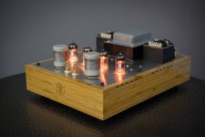
This amp is 3w stereo design for sensitive speakers.
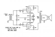
It’s intentionally super simple. It uses a interesting Russian signal pentode with a dual plate design. There seem to be a lot of these available at reasonable prices.
It’s cool because it’s got fairly high gain and transconductance when triode strapped. The gain is high enough to be driven to clipping with less than 8v p-p.
I also had a really nice pair of vintage 1:5 600:15k Ampex transformers I wanted to use in a project.
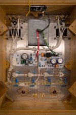
The PS is regulated 230v and 6.3v.
The outputs are a AliExpress purchase and are the weak link. Though they perform fine at 3w.
Distortion isn’t exactly low and depends on if you can find a well matched pair of tubes. .5-1% at 1w rising to 3% at visible clipping at 3w.
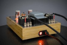
The power transformer I used is a old Triad organ pull. I’d change this if I could do it again. It has a slight buzz and coupled to the output transformers even though they orientation is correct for lowest hum. This basically undoes all my work regulating everything and my s:n is back to 75-80db vs 1w. Oh well. The toroids I normally use have way less issues coupling to outputs.
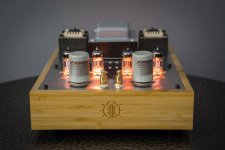
The excellent box is made of bamboo and my friend Sean used his CNC to create it.
This amp is 3w stereo design for sensitive speakers.
It’s intentionally super simple. It uses a interesting Russian signal pentode with a dual plate design. There seem to be a lot of these available at reasonable prices.
It’s cool because it’s got fairly high gain and transconductance when triode strapped. The gain is high enough to be driven to clipping with less than 8v p-p.
I also had a really nice pair of vintage 1:5 600:15k Ampex transformers I wanted to use in a project.
The PS is regulated 230v and 6.3v.
The outputs are a AliExpress purchase and are the weak link. Though they perform fine at 3w.
Distortion isn’t exactly low and depends on if you can find a well matched pair of tubes. .5-1% at 1w rising to 3% at visible clipping at 3w.
The power transformer I used is a old Triad organ pull. I’d change this if I could do it again. It has a slight buzz and coupled to the output transformers even though they orientation is correct for lowest hum. This basically undoes all my work regulating everything and my s:n is back to 75-80db vs 1w. Oh well. The toroids I normally use have way less issues coupling to outputs.
The excellent box is made of bamboo and my friend Sean used his CNC to create it.
Attachments
-
 75D0A876-E59B-4DBA-AD0B-61FE06FF0EE7.jpg492.8 KB · Views: 429
 -
 C3C644FB-807C-456D-A025-C9EBD15714EC.jpg562.8 KB · Views: 375
 -
 B0E60E95-DDF5-4C3B-80EC-A0C35BBB5680.jpg527.2 KB · Views: 361
 -
 AF67993F-E571-4D9D-9EE8-A624273D4524.jpg670.1 KB · Views: 399
 -
 B0A3AFC1-A8C8-45DC-A8AB-1C9324482CBC.jpeg60.1 KB · Views: 508
Congratulations on a super nice build, the general level of construction looks top drawer 🙂 and the bamboo with those little ventilation slits just sets the whole thing off.
Fantastic
Fantastic
Thanks! The vents are a funny story that goes like this. I finished building the whole circuit onto the top plate and realize I haven’t put any ventilation holes in. So I asked Sean if there was anything he could do with the box.
Came out so nice might do it that way again! ��
Came out so nice might do it that way again! ��
It certainly has come out nice.
I would be afraid of the wood splintering so to be able to do it so neatly once it was all done is great... but I guess like everything, having the right tools for the job makes the impossible possible.
I would be afraid of the wood splintering so to be able to do it so neatly once it was all done is great... but I guess like everything, having the right tools for the job makes the impossible possible.
Thanks! It was a bit of a experiment for this build. I’m happy with how it came out. Though on a more crowded build it might not work as well.
Very interesting using a virtual ground to get the antiphase as opposed to an input Transformer with a CT. A few weeks ago I posted on problems I was having using a center tapped secondary as a phase Inverter. Where one side would go off balance as frequency rose. I tested 4 different transformers and all of them went off balance. But when I used a virtual ground like this, both sides of the phase stayed perfectly matched amplitude wise to over 200 kHz rock solid. The whole purpose of my experiment was to try doing a Transformer phase Splitter. Now I see an actual build set up and working this way.
Well these don’t have a center tap so I didn’t even try it. Probably the reason your center tapped transformers were shifting is the DCR of the secondary on either side of the center tap are different. In any case the “Virtual Ground” works just fine.
Nice build, congrats!
Did something similar (much less pretty though 😀) about 10 years ago.
Monacor LTR-110 transformers wired as 1:1+1, fixed bias with CR2032 between the Monacor's secondary CT and the ground, 6J43P's g3 tied to the plate.
It was quite a decent desktop amp...
Did something similar (much less pretty though 😀) about 10 years ago.
Monacor LTR-110 transformers wired as 1:1+1, fixed bias with CR2032 between the Monacor's secondary CT and the ground, 6J43P's g3 tied to the plate.
It was quite a decent desktop amp...
I silenced a few vintage buzzing power transformers like the one you have by putting cloth tape on the inside face of the bells, to avoid direct contact between wires and bells; and between bells and laminations. Worked pretty well for me, but YMMW. I used the readily available cloth tape sold to wrap wire bundles inside car dashboards, and it smells a little bit when temperature rises. Maybe a more expensive/specialized one will fare better at high temperatures.
I also often use bamboo wood lately. My woodworking capability is very limited, and bamboo is the hardest wood that don't cost a fortune. No need to use wood drill bits and files; the ones I use for aluminium chassis works perfectly. Bamboo does not splinter, it behaves almost like a metal.
I also often use bamboo wood lately. My woodworking capability is very limited, and bamboo is the hardest wood that don't cost a fortune. No need to use wood drill bits and files; the ones I use for aluminium chassis works perfectly. Bamboo does not splinter, it behaves almost like a metal.
Nice build, congrats!
Did something similar (much less pretty though 😀) about 10 years ago.
Monacor LTR-110 transformers wired as 1:1+1, fixed bias with CR2032 between the Monacor's secondary CT and the ground, 6J43P's g3 tied to the plate.
It was quite a decent desktop amp...
g3 tied to the plate!? That’s very interesting because g3 in this tube is definitely a beam forming plate. How did that effect the performance?
That’s a good idea biasing the transformer secondary but I’d probably go the opposite way and put a positive V on it so I could use a couple bypassed current sources on the cathodes and drop sufficient V there. Then I’d have a easy time balancing dc in the core of my output tx. I did something like that actually with a more recent 6e5p design.
I definitely agree that placing something in the end bell, perhaps some high temp silicone, would quiet it a bit mechanically. I’m more annoyed about it coupling to my outputs though. Oh well!
It makes rp (and mu) a bit lower, and it makes the sounds a little bit more bright and harsh (which was good for the very mellow sounding speakers I used with this amp, but YMMV)g3 tied to the plate!? That’s very interesting because g3 in this tube is definitely a beam forming plate. How did that effect the performance?
If a tube has a separate connection to the Beam Formers, and you tie it to the plate, then a very good portion of the current goes to the Beam Formers, not to the plate.
The Beam formers are closer to g2, g1, and the cathode than the plate is.
And the Beam formers have a relatively large area, that purposely shields much of the fields from the plate.
Fields Rule!
If a tube has a separate g3 (suppressor grid) connection (EL34), and you tie it to the plate, the only thing that keeps g3 from hogging much of the current is the extremely low area of g3.
The Randall amplifier project (in the main park of San Francisco, CA), tied g2 and g3 to the plate of an EL34. That is the only time I have seen that topology.
Lots of imagination for that one.
The schematic in Post # 1 shows g3 connected to the cathode, and a resistor from g2 to the plate.
Last edited:
Hey Doug, once again: super nice build 🙂
Greets,
Bart
Thanks man!! 😀
The schematic in Post # 1 shows g3 connected to the cathode, and a resistor from g2 to the plate.
Yea, in my circuit I just tied g3 to cathode. It never occurred to me to try connecting it to the plate. In these tubes there’s enough gas that it’s easy to see the electron beam hitting the plate in a perfect rectangle formed by the beam forming plate. Seems like it would pull a lot of current through the beam forming plate to tie it the plate. But that might actually slightly increase it’s current and dissipation ability as it’s basically extra plate area I guess. I may try it and measure the effect.
- Home
- Amplifiers
- Tubes / Valves
- 6J43P, single stage, transformer coupled, push pull, 3w amp.