Post #7 in this thread might answer the question (except for the highly questionable break resistor)
Also seems to point in the direction of idea #2.
I'll see if I can work that out a bit more...
What do you all think about grounding the buss at the power supply side and attaching the input jack ground to the point where the first stage cathode attaches to the buss?
If your aim is for no discernible hum, then I'd suggest go with the simplest setup for starters and test using your speakers, as many diyers have found (including commercial equipment) that simple grounding without intentional ground loops is fine. The caveat is that you haven't identified what is connecting to this amp, as the total system could be the issue, rather than just your amp configuration.
Schematics can show multiple types of ground symbols, including just one symbol but adding a number or asterix next to a symbol, to show where a star connection is actually made - that can be very insightful. At the moment, connecting a ground symbol to the negative leg of the bridge diode is a poor star point to use. Perhaps have a go at updating your schematic to what you think will work, and then some more focussed discussion can follow.
Idle current balance helps keep output transformer DC current imbalance close to zero, which is known to minimise low frequency distortion and extend low frequency response due to the output transformer. The gain of each phase (side) of the push-pull configuration, varies due to individual valve parameters (simplistically the gains of V1 x V4 should match the gains of V3 x V2) - which you are only likely to match by tube rolling, along with more instrumentation that you presently have (and a good scope is likely not be the most appropriate type of instrumentation for distortion and noise assessment).
Heater circuit configuration (not just how heater wiring is twisted) has the risk of introducing hum in to the signal path, which you may not be able to discern versus grounding related hum or noise (until you do a battery powered heater type test).
Last edited:
Also sounds like idea #2/Blencowe. I might be missing something...
I'm not convinced #2 is wrong. I think the primary loop would be from input ground through the star to safety and back to the source. I don't think that changes if you connect input ground to the low current end of your bus or directly to the star point.
I'm not offering the above as fact, just trying to learn something along the way.
Thanks trobbins, for your eleborate replies; much appreciated. I'm afraid I'm not knowledgeable enough to fully understand the consequences of the hints you give. Never the less: please keep 'm coming. I'm here to learn!
Ok, let's at least start with the simplest setup, but what is the simplest setup?
I'm planning to buy a good budget dac (e.g. $100 Schitt or Topping) connected via usb to a raspberry pi 4.
New to me that schematics are used that way, but if it helps I'll do it. Need to find some time. Kinda hectic the last days with kids, corona tests, quarantine. Test was negative, kids back to school, so more free time ahead. If only the daytime job didn't cost that much time...
I'm thinking about matching components for the CCS bias. That should cover the DC current (im)balance, right? W.r.t. gain, that will have to wait for later. This (first hifi tube) amp is supposed to be a decent platform for further exploration of the tube hifi world.
I'm not sure what you mean by heater circuit configuration. All I know is from Blencowes book: twist, keep away from sensitive circuits, cross at right angles, jump straight over at the sockets, maybe elevate and use DC if you have to. Going for AC for now. Detailed design/implementation in a layout will come after this grounding thingy.
If your aim is for no discernible hum, then I'd suggest go with the simplest setup for starters and test using your speakers, as many diyers have found (including commercial equipment) that simple grounding without intentional ground loops is fine. The caveat is that you haven't identified what is connecting to this amp, as the total system could be the issue, rather than just your amp configuration.
Ok, let's at least start with the simplest setup, but what is the simplest setup?
I'm planning to buy a good budget dac (e.g. $100 Schitt or Topping) connected via usb to a raspberry pi 4.
Schematics can show multiple types of ground symbols, including just one symbol but adding a number or asterix next to a symbol, to show where a star connection is actually made - that can be very insightful. At the moment, connecting a ground symbol to the negative leg of the bridge diode is a poor star point to use. Perhaps have a go at updating your schematic to what you think will work, and then some more focussed discussion can follow.
New to me that schematics are used that way, but if it helps I'll do it. Need to find some time. Kinda hectic the last days with kids, corona tests, quarantine. Test was negative, kids back to school, so more free time ahead. If only the daytime job didn't cost that much time...
Idle current balance helps keep output transformer DC current imbalance close to zero, which is known to minimise low frequency distortion and extend low frequency response due to the output transformer. The gain of each phase (side) of the push-pull configuration, varies due to individual valve parameters (simplistically the gains of V1 x V4 should match the gains of V3 x V2) - which you are only likely to match by tube rolling, along with more instrumentation that you presently have (and a good scope is likely not be the most appropriate type of instrumentation for distortion and noise assessment).
I'm thinking about matching components for the CCS bias. That should cover the DC current (im)balance, right? W.r.t. gain, that will have to wait for later. This (first hifi tube) amp is supposed to be a decent platform for further exploration of the tube hifi world.
Heater circuit configuration (not just how heater wiring is twisted) has the risk of introducing hum in to the signal path, which you may not be able to discern versus grounding related hum or noise (until you do a battery powered heater type test).
I'm not sure what you mean by heater circuit configuration. All I know is from Blencowes book: twist, keep away from sensitive circuits, cross at right angles, jump straight over at the sockets, maybe elevate and use DC if you have to. Going for AC for now. Detailed design/implementation in a layout will come after this grounding thingy.
Attachments
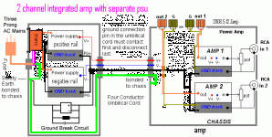
That hifonix diagram is likely not compliant to safety standards in some countries, due to multiple connections being made to the main protective earth terminal.
Here's another go at it (attachment).
PCB has two connected local star ground. So a true single bus is not possible. However, I think I made effectively single bus by routing the grounds in one line, with the input ground jumping down alongside the pcb ground trace between pp and ltp. I had to move the inputs to between the input and output tubes. It has to cross a heater; no free lunch... The inputs are tied together and connected to ground via a capacitor. Connection of ground to the chassis is via a hum-loop block network. Pretty much the hifi sonix way. Safety ground is near the iec input.
I'm still thinking about where to put the hum breaking resistor.
And again: fire at will!
Attachments
Why do you think a 0V link is needed between the input sockets? Is it a combined input socket, where the grounds can't be separated?
Why do you think a 0V link is needed between the input sockets? Is it a combined input socket, where the grounds can't be separated?
The hifisonix advices it. See page 35 to 38 of http://hifisonix.com/wordpress/wp-content/uploads/2019/02/Ground-Loops.pdf .
Ok so now you are considering a total system including external signal sources - are those external signal sources identifiable (eg. a preamp, or cd player or ...) ? Have you looked at how they manage their grounding?
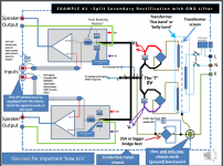
One aspect of the hifisonix presentation is that it is focussed on solid-state amplifiers, where the influence and mix of hum and noise sources can sometimes lead to different control methods being more influential than other available methods, especially with respect to the order of magnitude (or more) difference between input signal impedances. When or if you get down to testing your amp to a level where you can identify hum and noise levels (ie. a spectrum plot that goes down to the noise floor of the equipment), then it can be helpful to be able to step through individual changes to how your amp is set up and gauge any differences. For example, if the input sockets are a combo where the grounds are solidly linked, then you don't have the easy opportunity to split the grounds.
One aspect of the hifisonix presentation is that it is focussed on solid-state amplifiers, where the influence and mix of hum and noise sources can sometimes lead to different control methods being more influential than other available methods, especially with respect to the order of magnitude (or more) difference between input signal impedances. When or if you get down to testing your amp to a level where you can identify hum and noise levels (ie. a spectrum plot that goes down to the noise floor of the equipment), then it can be helpful to be able to step through individual changes to how your amp is set up and gauge any differences. For example, if the input sockets are a combo where the grounds are solidly linked, then you don't have the easy opportunity to split the grounds.
Last edited:
Input grounds are not solidly linked. I get your point of measuring the influence of the various add-ons. Is the layout in #31 (with the input not connected) a good basis to start with?
Btw, I've found no grounding info on the dac's I'm considering.
Btw, I've found no grounding info on the dac's I'm considering.
Likely the most accessible and understandable reference due to a focus on valve amps, and excellent descriptions and diagrams is Merlin's section on grounding. http://www.valvewizard.co.uk/Grounding.pdf
a. which was probably taken from one of KOC's tons-of-tone books. Sure reads like the way KOC writes...........
b. secondly, I don't use star grounding because is more of a band aid, and does not address the real root cause of conducted hum and noise for either a guitar amp or a HiFi amp.......but the Valve Lizard misses the bullseye on this one as well........
It's possible to put separate chokes (or even just small resistors) in the B- paths from common power supply to separate channels' "ground busses". Even small impedances there are large compared to the other end of the ground busses being tied together somewhere.
Incidentally, that somewhere doesn't need to be inside your new amplifier; it could be back at the preamp (source) end of incoming signal wires. Some advantages accrue from standing input signal "ground" off from chassis by even 10 Ohms each.
There is no such thing as "ground". Unless you're falling off a ladder.
Chris
ps: There's been a rash lately of mean and ignorant comments. It's not at all the usual on diyAudio, and will pass. Please don't give us up.
For the benefit of any lurkers who may be a little baffled by the recent exchanges, Mooreamps is a known agitator from guitar amp forums. I suspect he has been banned again and has sailed over to this forum for a while.ps: There's been a rash lately of mean and ignorant comments. It's not at all the usual on diyAudio, and will pass. Please don't give us up.
Merlinb, while I spot you here...
Thanks for having your website, I learned a lot from it over the years! your PDF about grounding should be mandatory reading material for anyone building their first amps http://www.valvewizard.co.uk/Grounding.pdf
Thanks for having your website, I learned a lot from it over the years! your PDF about grounding should be mandatory reading material for anyone building their first amps http://www.valvewizard.co.uk/Grounding.pdf
- Home
- Amplifiers
- Tubes / Valves
- Yet another grounding thread