Here is a little, simple amp that turned out to be easy to build,
and with decent parameters.
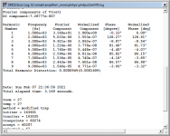
It's based on Philips AH578 (which was a quasi amp), originally designed by Earl Rapp, but built with modern devices (LT1056 op-amp, Exicon dual-die FETs). Rails at 45V.
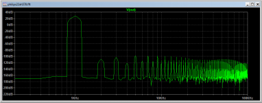
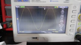
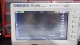
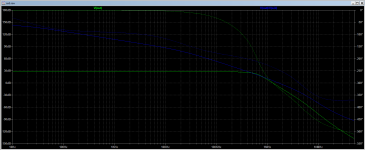
All screenshots taken with 8 Ohm load.
DC offset at the output: 2mV, and stable.
Idle current: 80mA per device.
PCB design: post #13
HexFet version of the amp: post #124
PCB design for HexFet version: post #130
Push Pull HexFet version (fast and stable): post #1
...
and with decent parameters.
It's based on Philips AH578 (which was a quasi amp), originally designed by Earl Rapp, but built with modern devices (LT1056 op-amp, Exicon dual-die FETs). Rails at 45V.
All screenshots taken with 8 Ohm load.
DC offset at the output: 2mV, and stable.
Idle current: 80mA per device.
PCB design: post #13
HexFet version of the amp: post #124
PCB design for HexFet version: post #130
Push Pull HexFet version (fast and stable): post #1
...
Attachments
-
 philips22ah578.jpg232.4 KB · Views: 3,226
 -
 1khz_thd.png23.5 KB · Views: 3,068
 -
 1khz_fft.png19.6 KB · Views: 2,283
 -
 sinus_1khz.JPG235.8 KB · Views: 2,149
 -
 sinus_34khz.JPG225.4 KB · Views: 2,000
 -
 sinus_100khz.JPG241.1 KB · Views: 596
 -
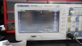 square_1khz.JPG241.2 KB · Views: 612
 -
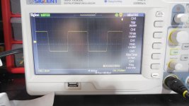 square_14khz.JPG229.9 KB · Views: 646
 -
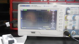 square_34khz.JPG232.6 KB · Views: 1,436
 -
philips22ah578.asc10.4 KB · Views: 262
Last edited:

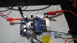
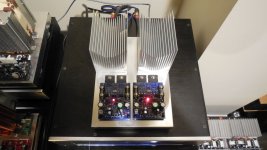
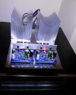
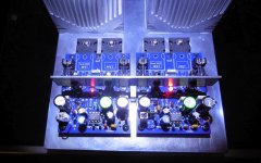
Here is actual build.
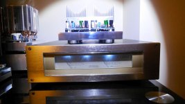
Mounted on Alu chassis, with external PSU (with speaker protection and VU meters).
Heatsinks are adopted from Dell 4U server. ($6 each from Ebay).
PCB was originally designed for smaller devices (single die), but finally I went with dual-die Exicons, and they turned out little bit bigger..
Mounted on Alu chassis, with external PSU (with speaker protection and VU meters).
Heatsinks are adopted from Dell 4U server. ($6 each from Ebay).
PCB was originally designed for smaller devices (single die), but finally I went with dual-die Exicons, and they turned out little bit bigger..
Attachments

Excellent measured and CRO waveform, not to mention the elegant implementation. Clearly a very linear design even before applying nfb. What is the loop gain?
Looks to have no evident faults. What is the clip, Minek?
Looks to have no evident faults. What is the clip, Minek?
>What is the clip, Minek?
Wasn't able to reach clip on my lab PSU.
Usually it runs out of juice before clipping.
Will have to re-test for clipping on my living-room linear PSU.
I finished final assembly late last night..
Wasn't able to reach clip on my lab PSU.
Usually it runs out of juice before clipping.
Will have to re-test for clipping on my living-room linear PSU.
I finished final assembly late last night..
On the photos the heatsinks look unusually tall. Must be the camera distortion...
They are not that tall in reality..
They are not that tall in reality..
Been listening to the new amp whole day.
Sounds excellent.
Cooling is more than adequate, Dell heatsinks work very well.
Sounds excellent.
Cooling is more than adequate, Dell heatsinks work very well.
Due to several inquires, I'm attaching here Sprint Layout design for the PCB.
PCB has 2 separate ground connections:
a) signal
b) dirty
These are NOT connected together on the PCB.
I run two separate wires from the PSU's ground to the PCB, one for a) and one for b).
Pinout for small transistors fits KSA992 type (BCE), however it's very easy to fit 2N5551 type pinout (CBE), they just need to be rotated slightly. Silkscreen clearly marks B,C and E holes.
R20/R22 need to be 1W
R18 : 2W
Q1/Q2 most likely can be replaced by KSA992/KSC1845
C5/C6 - small ceramic X7R 50V
C7 bipolar, 6V3 or 10V
C9/C12: 50pF - most likely this value can be lower (E.g. 33pF), I was just happy enough with oscilloscope results at 50pF, so didn't want to bother changing it to try lower values..
If using different latfets, gate stoppers R15/R16 may need to be re-adjusted depending on input capacitance of fets.
C1 in the original Philips amp was 100uF. 10uF is enough, but in my build I did use 100uF polar.
If C1 is polar, minus should be at the op-amp side.
When testing, set to Idle_Pot initially to minimum value to minimize idle current.
Attachments
Last edited:
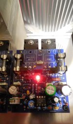
Model used for RED led was Liteon LTL1CHKEKNN.
1.6V drop at 1mA, according to the sim.
In actual build - random red LED from China was used.
Easy to adjust resistor R19 to get the right biasing, if using different diode(s).
1.6V drop at 1mA, according to the sim.
In actual build - random red LED from China was used.
Easy to adjust resistor R19 to get the right biasing, if using different diode(s).
Last edited:
Please explain your choice of R3, 4, 6 and 8, thanks.
All starting values for the input/vas stage were preserved from original Philips design.
Then tweaked for different rail voltage (original was running at 78V, and 4 output pairs of N bjt devices).
Then, tweaked for optimal Thd, FFT profile, square waves ringing and clipping behavior.
R4 (along with R6) defines gain - so it depends on your input voltage, and expected power you want to squeeze from this amp.
Original value was 220 Ohm, lowered to 150 to get around 100W of honest power from 1.2V input signal.
R3 was lowered from 2k to 1k to lower distortions, and C15 (missing in the original) was added to help handling square waves response.
R6, R8 value was preserved from original Philips design.
R8 values don't affect any measurements in any visible way..
Last edited:
Thank you Minek!
That is a very impressive design........
HD
Kudos go to Earl Rapp, I just tweaked few components here and there.
- Home
- Amplifiers
- Solid State
- LatFet Amp Based on Philips AH578