> Connecting directly to the PCM63 chips will change the nature of the dac as you will be bypassing the digital filter.
Even if you wish to keep a PMD100 in between, the I2SoverUSB will still support LJ output as required by the PMD.
Patrick
Even if you wish to keep a PMD100 in between, the I2SoverUSB will still support LJ output as required by the PMD.
Patrick
I don't use USB as source.
It is fundamentally foul, as it is not synchronised.
And then people invent all sorts of work-around to solve that.
I rather use a synchronised source in the first place.
I bought the JLSound just to be able to measure single chip distortions.
It was part of a measurement instrument, not a musical one.
Patrick
For a few years I sat next to an interface chip designer at my daughter’s karate lessons. I talked about designing a usb dac with him. His response was why? He said it was designed for mice and keyboards and everything else was bandaids put on top. I don’t know if that is really true but I am happy to buy someone else’s dac and not have to invest the time.
This is the solution I use.
ultimate source
There are modern versions with dual clocks at 22 & 24MHz, etc.
But the key point is you drive the processor and the DAC with the same clock.
IMHO no better solution.
A 16GB SD card can store almost 20 hours of music.
I don't need access to TB disks.
Patrick
ultimate source
There are modern versions with dual clocks at 22 & 24MHz, etc.
But the key point is you drive the processor and the DAC with the same clock.
IMHO no better solution.
A 16GB SD card can store almost 20 hours of music.
I don't need access to TB disks.
Patrick
Yes, there is magic in SD card player as source and it is very hard to beat it with usb. Using that with the i2s lines reclocked gives a really excellent solution. Simpler the SD player the better I think.
However, USB can be very good with dedicated source, even if not the last word.
However, USB can be very good with dedicated source, even if not the last word.
> Connecting directly to the PCM63 chips will change the nature of the dac as you will be bypassing the digital filter.
Even if you wish to keep a PMD100 in between, the I2SoverUSB will still support LJ output as required by the PMD.
Patrick
I know. I have the JLSounds board. However, the OP has the SM5847.
Everyone and his dog thinks they have the ultimate solution. The only thing I haven't seen is a player that holds the disc steady and spins everything else.
The name was not invented by me.
And I still think it is the best technical solution, whatever the name.
But this is DIY.
Everyone is free to choose what he likes.
Cheers,
Patrick
And I still think it is the best technical solution, whatever the name.
But this is DIY.
Everyone is free to choose what he likes.
Cheers,
Patrick
Yes you could input SPDIF with the XMOS board.
With the JLSounds board, you would input into U11-A, -B, -C for the right channel and similar for the left channel.
http://www.jlsounds.com/uploads/I2SoverUSB v.III.pdf
Mmmmm. So the JLsounds board arrived safe and sound and super quick. On first try I get only noise from the DAC. I believe I have the i2soverusb board connected correctly (triple checking) and the manual is pretty clear. Nothing only low level noise from the dac though. I was connecting it into U4 and U11 CLK, LE and Data L/R as appropriate. Software was recognising the board and I did a quick and dirty check, and there was some signal on each line to U4 and U11 (I do not have a scope, so this was just measuring the signal as if it was DC - not ideal but at least you know something is going). Just to check the i2soverusb I configured it for SPDIF and it works fine with that.
I need to think about this a bit more.....
Yes - but I think I have found an error in one of my connections - I will try again tomorrow evening....
So I have found one issue, but need some assistance on another. The first mistake was all mine - I was using a later revision of the board schematics, from the version after the one I have. So that was never going to work out. However, I have the right one now and just need a little direction as I'm ignorant as hell of implementation in these dacs.
So going back to Ben Mahs post above, the idea is to use the i2soverusb board which is configurable to output CLK, LE and Data L/R to the PCM63. As he mentioned, the i2soverusb output can be sent to U4 and U11. But when I do this, I get some background noise only. I have been connecting these lines on the inputs to U4/11 - should I be connecting them to the outputs instead? I've added the schematic here with arrows to show what I mean.....
Apologies in advance for what is probably an elementary question.
Attachments

I remember having to configure the USB Audio Device in Windows with the correct resolution first.
Cheers,
Patrick
Cheers,
Patrick
Ok, just did a check there, system I am using (linux, see wtfplay-project.org) says it does not change native res of the file..... and the source material here is all 16/44.
Inputs to the Input side (left side).
http://jlsounds.com/uploads/I2SoverUSB v.III.pdf
Instructions for board.
Jumpers and 4.7k resistor for PCM63 shown in diagram.
Also instructions for powering the board.
Pictures of your setup may help in trouble shooting.
http://jlsounds.com/uploads/I2SoverUSB v.III.pdf
Instructions for board.
Jumpers and 4.7k resistor for PCM63 shown in diagram.
Also instructions for powering the board.
Pictures of your setup may help in trouble shooting.
Yes - i2soverusb is configured:
4.7k from H1.1 to H1.3
Bus power to USB side, separate supply to H3.17/H3.19
Jumper 4 closed, no other jumpers closed
Then taking outputs from i2soverusb to DAC 74hc86
H3.9 (DOR) to U11 pin 10
H3.13 (DOL) to U4 pin 10
H3.15 (LE) to U4 and U11 pin 4
H3.11 (CLK) to U4 and U11 pin 1
H3.16 (gnd) to a ground point on the DAC board
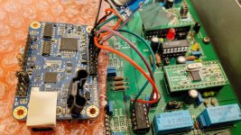
Photo attached of connections to U4, U11 is the exact same. GND point goes to ground point in the receiver section out of shot.
In the later revision (my first mistake) the inputs on U4 and U11 are different, but on this version they are the same on both.
4.7k from H1.1 to H1.3
Bus power to USB side, separate supply to H3.17/H3.19
Jumper 4 closed, no other jumpers closed
Then taking outputs from i2soverusb to DAC 74hc86
H3.9 (DOR) to U11 pin 10
H3.13 (DOL) to U4 pin 10
H3.15 (LE) to U4 and U11 pin 4
H3.11 (CLK) to U4 and U11 pin 1
H3.16 (gnd) to a ground point on the DAC board
Photo attached of connections to U4, U11 is the exact same. GND point goes to ground point in the receiver section out of shot.
In the later revision (my first mistake) the inputs on U4 and U11 are different, but on this version they are the same on both.
Attachments
Looking at the schematics in 63v3_3.pdf, U11 is right channel. Left channel is not shown but I assume the equivalent is U4 from what you have written.
According to the schematics, for right channel, D0R (H3.9) goes to pin 10 of U11, and D0L (H3.13) should go to pin 10 of U4.
LE (H3.15) should go to pin 2 of U11 and U4.
CLK (H3.11) should go to pin 5 of U11 and U4.
According to JLSounds instructions, for PCM63, J4 and B5 should be closed. Edit: Not sure now about B5 re: on-board or external oscillators. If everything is connected correctly and still doesn't work, try B5 closed.
Also remove SM5847 as rfbrw suggested.
According to the schematics your DAC is balanced so there are two PCM63 per channel, and U11 feeds the right channel, and U4 feeds the left channel.
Last edited:
Remove the SM5847 from the socket and see if that helps.
By George, he's got it!!
Yes removing the SM5847 fixed the issue and it seems to working well now.
Ben Mah - those U4/U11 pinouts are from the next revision of the boards I have (I made that mistake)....
But anyway, I have to say a huge thanks to all you guys for your really REALLY helpful suggestions. Sincere appreciation and thanks.
Fran
- Home
- Amplifiers
- Pass Labs
- Pass D1 - using i2s input