Youtube - Waterjet Cutting Wood - but unusable for JN's need due to moisture sensitivity.The pressure involved would turn is to pulp I would think. As soon as it hit the surface it would be deflected by and follow the grain?
Last edited:
Lots of folks have big CNC routers for furniture making. By the time invested, it's not a bad plan to job it out.
Where is the fun in jobbing it out?
Learning how to move a CNC using G code, learning the ups and downs of upspiral/downspiral, feed rate, cut depth, structure integrity.... THAT is what it is all about...well, ok, the electronics, mechanics, and code are fun too...😉
The best one can do is get involved in far more projects than you can possibly do in your lifetime.
If you live long, you do a lot. But regardless, you never die of boredom.
Jn
Last edited:
Youtube - Waterjet Cutting Wood - but unusable for JN's need due to moisture sensitivity.
That was some major thick wood, really cool.
Jn
I assume the aspect ratio comes into play. No idea the hole diameter to thickness ratio ed needs, so no idea if etching is viable for him.I would think photochemical machining would be the best option for something like that:. Precision Chemical Etching - Photochemical Machining - Wet Etching | Fotofab
It does provide bigger scale though, assuming ed can handle breakout tangs...I would think a pair of trim dykes would be sufficient for "depaneling".
Jn
Where is the fun in jobbing it out?
As someone who's afflicted the same disease, when the thing you need to make is bigger than your CNC can do in a single setup, it's a world of pain to re-register. 🙂 This is a case of, "some people in the world exist so others can learn what *not* to do"
If you can do it in a single setup, rock on!
Last edited:
If you're OK with the draft angle then photo etch is greatI would think photochemical machining would be the best option for something like that:. Precision Chemical Etching - Photochemical Machining - Wet Etching | Fotofab
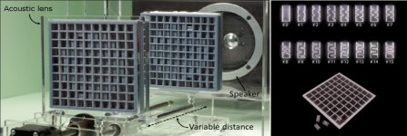
I find the math to design an acoustic lens using a hole pattern apparently not covered in any literature I have found. Thus it was a challenge to design the hole sizes and pattern. I hesitate to think what a non-uniform hole will really do to the pattern. I was surprised to see the effect of the melted tails. It was a biggie!!!
However as I am producing the lenses right now by the thousands I will consider some prototypes to evaluate.
Currently the test method is to drill holes in a softer material.
The other issue is placing the microphone element at the correct focal point. This actually helps determine the lens design as the spacers used to fix the distance are way less expensive if you stick to stock sizes. As the hole pattern must be done by creative means that doesn't influence cost changes.
Of course the humor is the other folks making microphones for this and similar applications have no idea that an acoustic lens even exists. Only one unit I have seen uses a small plate hole and that is probably to protect the microphone element from tampering.
Last edited:
If you're OK with the draft angle then photo etch is great
For this application I would laminate several layers. Actually layers separated by a gap and aligned just so could improve the performance I suspect. Think multi element lens. They would also be a pretty effective filter, calculating the cutoff frequency would require some serious processing I think.
The Neuman U47 microphone screen is another example of this, very poorly understood, but I'm told you need to duplicate the wire meshes exactly to get the same response if you are making a copy. Even a small change makes a very noticeable difference.
Last edited:
Demian,
Pretty sure a gap between elements will completely screw things up. Just based on feel from seeing what the melted tails did!
Does show you are thinking, a good thing and too rarely done.
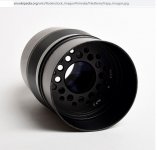
The most common acoustic lens is of course composed of parallel plates and is sort of adjusted on one axis by the notch shape in the plates.
Hole patterns allow more uniform circularity. The issue becomes efficiency or from optics f number.
Although I have patents in the works on the products, the design technique is not patentable. Interestingly enough the closest microphone patents I found made claims of using diffraction to tighten the patterns! I think this derives from shotgun microphone designs where the holes/ports are perpendicular to the wave image.
The one I think is actually valid is from EV for using rear facing hole patterns to reduce proximity effect in directional microphones.
Pretty sure a gap between elements will completely screw things up. Just based on feel from seeing what the melted tails did!
Does show you are thinking, a good thing and too rarely done.
The most common acoustic lens is of course composed of parallel plates and is sort of adjusted on one axis by the notch shape in the plates.
Hole patterns allow more uniform circularity. The issue becomes efficiency or from optics f number.
Although I have patents in the works on the products, the design technique is not patentable. Interestingly enough the closest microphone patents I found made claims of using diffraction to tighten the patterns! I think this derives from shotgun microphone designs where the holes/ports are perpendicular to the wave image.
The one I think is actually valid is from EV for using rear facing hole patterns to reduce proximity effect in directional microphones.
Youtube - Waterjet Cutting Wood - but unusable for JN's need due to moisture sensitivity.
Interesting, "abrasive water jet", does that mean something is added to the water?
 Ed.
Ed.Something like that?
Design and characterization of an acoustic composite lens with high-intensity and directionally controllable focusing | Scientific Reports
Work c/out with ultrasonics (a lot of papers and pattents), now gets a step towards acoustic frequencies thanks to published books about Acoustic Metamaterials and by the use of 3D printing.
University of Sussex presented a paper in 2019 “VARI_SOUND: a vari-focal lens for sound”, can’t find it anymore.
(A diaphragm of acoustic metamaterial at varying distance in front of a loudspeaker cone acted like a trimmable sound collimator, see attachment).
George
Attachments
George, as the best internet cite source ever known, those cites are for limited bandwidth three dimensional lenses. My design is more based on producing what is effectively a hologram of a lens in only two dimensions.
Thanks.
Thanks.
I am confident that you are driving your design some distance ahead of the rest in the field. 🙂
I have the curiosity to look into one of these two books
Acoustic Metamaterials - Negative Refraction, Imaging, Lensing and Cloaking | Richard V. Craster | Springer
Error - Cookies Turned Off
George
I have the curiosity to look into one of these two books
Acoustic Metamaterials - Negative Refraction, Imaging, Lensing and Cloaking | Richard V. Craster | Springer
Error - Cookies Turned Off
George
By the time invested, it's not a bad plan to job it out.
Given that making clocks with wooden gears is one of the more masochist hobbies I think JN wants maximum pain and frustration from it.
Aside: Modern atomic clocks really do my head in. Not only the way the operate in their little casks of unobtanium but the fact time changes if you move the clock a few feet up or down.
Yes, I believe Garnet is commonly used as abrasive.Interesting, "abrasive water jet", does that mean something is added to the water?
If you use the CNC to create reference points through the work into the spoilboard, you can shift and pin the work at known offsets.As someone who's afflicted the same disease, when the thing you need to make is bigger than your CNC can do in a single setup, it's a world of pain to re-register. 🙂 This is a case of, "some people in the world exist so others can learn what *not* to do"
If you can do it in a single setup, rock on!
For example, if you are cutting a line array front panel with 9 4 inch drivers and 16 tweeters with a 2 inch square faceplate, the holes for the 4 incher screws could be the locators, using small pins.
My design will be vertical, and that would limit my ability to do that as the ceiling is under 6 foot in my basement.
But that made me think, if I make the CNC so that it can rotate, and add one leg that unfolds, I can store the CNC vertical, use it horizontal. Thanks for the idea...
Jn
Last edited:
If pain and frustration were my goal, then I am very good at it..😀Given that making clocks with wooden gears is one of the more masochist hobbies I think JN wants maximum pain and frustration from it. .
The desire is to provide enough energy to the pendulum to keep it moving without exceeding the strength of the wooden parts. Involute teeth are higher friction than cycloidal teeth. And cycloidal needs modification to tooth profile so as to limit engagement to the pitch circle as much as possible.
Measuring the delivered torque to the escape wheel is challenging, especially because the clock gears constantly switch from static friction to dynamic friction, and no lubrication can be allowed other than what the wood came with.
Aha!!! My current clock is a deadbeat escapement, which by design brings all the gears to a stop. If I add some recoil, then all the gears will back up a tad so when the pallets release the gears are already in forward movement and into dynamic friction. Hmmm, a little like de-tuning a car engine to accept lower quality gas...
Even brass movements have this static/dynamic issue, as the trick is to maintain a film of oil even when the arbors stop turning every click. Too thick, no click...too thin, metal wear.
Jn
Last edited:
Here's my solution to the question of whether to waterjet or not:
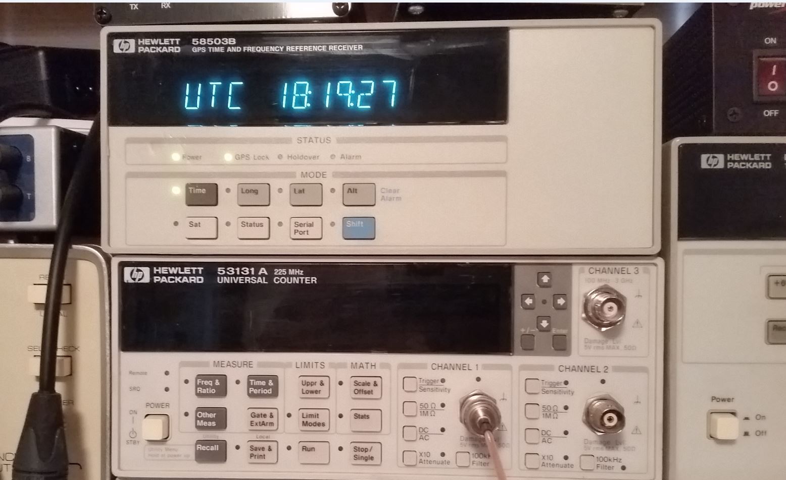
It usually acquires 5-8 satellites, and the reference 10 MHz output is accurate to 10 uHz 24 hr. stability, really helps the freq counter, spectrum analyzer and RF generator stay on frequency. And of course there is the ham rig which is now locked to it for whatever reason I do not know...it had a 10 MHz Ref. In jack, so I used it.
I think you would have to choose your wood carefully to achieve near that accuracy (ducks and runs....)
I have to say I admire your persistence wrangling such a squirmy material into a precision application! That is a labor of love! Whenever I have to cut wood precisely on the mill I laminate it with aluminum to prevent/reduce tearout. YMMV
Keep on keepin on!
Howie
- Home
- Member Areas
- The Lounge
- The Black Hole......