I have invested heavily in Amazon Echo and other Smart products and am trying to build a whole house sound system which is controlled by voice.
This is primarily for playing back radio and music from an Amazon Echo and is not meant to be "Hi-Fi" quality.
Four rooms have ceiling or wall mounted speakers all wired back to a single location. I was originally going to use a 4 way speaker switch but have had problems getting this working. I have decided rather than switch the output of a single amp which can cause impedance issues and overload of the amp, to instead use a separate 100+100w amp (overkill but better than driving a 30watt amp at higher volume) to each room and switch the sound source to each amplifier and pair of room speakers as required.
The amps I am using are cheaps as chips (under £10 each if bought directly from China) and based on TPA3116 chips like these.
The power to the amplifiers will be switched using a four way smart switch like this.
The output from these relays will also close one of four 35amp 12v relays which will connect and disconnect the amp(s) from the associated room speakers.
The desired effect will be to say "Alexa play Radio 4 in the Kitchen" or Alexa play smooth jazz in the dining room". This will close the appropriate smart relay powering the amp on the kitchen(or dining room) speakers and close the relay connecting the speakers to the amp.
This brings me to my question. Is it best to switch both the Line(+ve) and Ground lines to the speakers i.e. using DPST relays which will mean using four relays. Alternatively there are some nice solid state four way relay circuit boards which are only single pole if I could only switch the Line(+ve) rail and leave the ground permanently connected.
I suppose I could just leave the speakers connected to the amp and just switch the power to the amp but wondered if I would get a "thump" when the power was applied.
Any thoughts would be appreciated.
Fozzie
IMHO leave the amplifiers on (and connected to their speakers ) and switch the sources.
Insure all sources and amp inputs are at 0VDC and you should get no thumping during switching.
Use small signal relays.
Not a good idea to run a class d amp without load.
Insure all sources and amp inputs are at 0VDC and you should get no thumping during switching.
Use small signal relays.
Not a good idea to run a class d amp without load.
Thanks Dug,
Interesting option. I hadn't thought of doing it that way. I could use the smart relay just to switch the signal source.
Not that I am particularly concerned but what do you think the resting power consumption would be with four amps running continuously without an input signal?
Fozzie
Interesting option. I hadn't thought of doing it that way. I could use the smart relay just to switch the signal source.
Not that I am particularly concerned but what do you think the resting power consumption would be with four amps running continuously without an input signal?
Fozzie
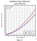
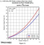
Although the amplifier you have selected ( others do as well ) suggests 100W + 100W The data sheet tells a more real story.
And although the amp ( you have linked to ) uses the chips in PBTL there will not be much more power than with "regular" BTL configuration until you decrease the load below 4R.
The usual downfall of these amplifiers are the power supply caps ( not too critical ) and the output filter inductors ( much more critical ).
And sometimes the pots are too high a value and allow or create noise issues.
Packaging and price are usually very good...can't compete with that.
If you like the sound then that is what really counts...enjoy.
just my $0.02
Attachments
Many thanks DUG for all your info.
Yes was aware that output was not 100w more like 75w max at 24v when driving 8 ohms speakers (according to another seller on ebay). I really don't need that sort of power, its mainly for background music and to listen to the radio.
Thanks for pointing me to the thread it makes interesting reading. It also describes noise from the pots.
I was actually thinking about unsoldering them and placing pots on the front of the existing enclosure. So I could change the values too. Any suggestion as to what value I should use?
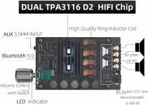
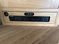
As an aside this is the 4 way speaker selector I was having issue with. It has internal matching transformers but I only got very low distorted sound out of it. I have therefore decided to use it as a case for the four amps and smart relay. Mainly as I went to a lot of trouble to build it in to my kitchen unit Shown with another 50W+50W TPA3116 based amp.
Yes was aware that output was not 100w more like 75w max at 24v when driving 8 ohms speakers (according to another seller on ebay). I really don't need that sort of power, its mainly for background music and to listen to the radio.
Thanks for pointing me to the thread it makes interesting reading. It also describes noise from the pots.
I was actually thinking about unsoldering them and placing pots on the front of the existing enclosure. So I could change the values too. Any suggestion as to what value I should use?
As an aside this is the 4 way speaker selector I was having issue with. It has internal matching transformers but I only got very low distorted sound out of it. I have therefore decided to use it as a case for the four amps and smart relay. Mainly as I went to a lot of trouble to build it in to my kitchen unit Shown with another 50W+50W TPA3116 based amp.
FozzieBear. You should have greater success attaching your images here - How to attach images to your posts.
Some sites don't like to be linked to. I tried to follow your link and saw this.
Some sites don't like to be linked to. I tried to follow your link and saw this.
Attachments

Does the 4 way switcher support BTL connections? ie no common ground between any of the speaker terminals and amplifiers.
Four amps would allow each room to have its own level.
I would use the lowest value of pot your source can drive.
If your source can drive 32 ohm headphones then I would use 200 ohm to 1K pots for each amp.
I would not recommend values above 10K.
I would use the lowest value of pot your source can drive.
If your source can drive 32 ohm headphones then I would use 200 ohm to 1K pots for each amp.
I would not recommend values above 10K.
Many thanks was having difficulty finding how to attach an image except via url. I notice you also cannot edit a post once posted so I couldn't go back and make the necessary changesFozzieBear. You should have greater success attaching your images here - How to attach images to your posts.
Some sites don't like to be linked to. I tried to follow your link and saw this.
Not sure but relay board has four isolated separately controlled single pole relays.Does the 4 way switcher support BTL connections? ie no common ground between any of the speaker terminals and amplifiers.
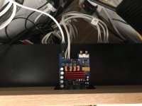
I have attached images of the TPA3116D2 schematic and one of the board itself for further info
Fozzie
Attachments
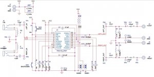

Your first post indicated that you are using TPA3116 modules. The schematic you displayed is for a TPA3122. The speaker negative terminal is common to both channels and ground.
The picture of the board is for a Dual chip TPA3116. The tpa 3116 each speaker output is about halfway between ground and the + power supply. The speaker negative outputs are NOT tied together and are NOT tied to ground. Connecting the - speaker terminals together and or to ground will most likely destroy the chip. You must use double pole switches for each speaker connection.
If you are only connecting one set of speakers to each amplifier and are switching the power supply connection on and off then you can use single pole switching.
The way I do this is have a dedicated Class D amp and speakers connected to each Amazon appliance in every room you want. You can tell Alexa to play music in any room even when you are in another room. If you have Spotify, you can link it to Alexa and have it pipe music to any room or all rooms. There is no electrical or electro mechanical “switch” needed. It’s all software and app controlled, as it should be.
Thank you xrk971 but this is not possible now as I have already spent a lot of time and effort bringing all the speaker connections to one location in my kitchen, where the amp and speaker selector are located. Attached are a few photos of my installation.
As the speaker selector won't work I aimed to remove the contents and mount the amps inside the case which would make a nice neat solution. Doug's idea of switching the power to each of the amps and keeping the speakers connected seems the best way forward.
However I am now looking to see how I can voice control a digipot (perhaps something like this ) to control the volume, as per a number of other threads on this forum.
I am trying to find a Tuya Smart relay board with a centre off similar to this to use for the voice control and to act as the two switches required for the circuit above. As I type this I have just thought perhaps I could just use a two relay board? One relay for volume up and the second for Volume down. Just need to check they work as momentary relays.
Fozzie
Attachments

OK so I have moved things on a bit since my last post. I have decided to use TDA7498 base amps in preference to the previous TPA3116 based amps partly because of the additional power output but mainly because I don't need bluetooth or volume control on each board. That said there are some 120w +120W TPA3116D2 based amps which I hadnt seen before. Any thoughts on which might be better suited would be apreciated. The TPA3116D2 are even cheaper than the TDA7498 boards 😀
Master volume control will be controlled below but individual amps will have a separate potentiometer.(Detailed schematic to follow)
I have attached a schematic for the amps and how they are each selected using a four way voice controlled Smart Relay board. The plan is I can use a voice command to say "Alexa turn on music in dining room" the appropriate relay will close providing power to the amp.
The other two channel Smart Relay will be used with a Maxim MAX5456 digipot to control the volume. This has the advantage over other digipots in that you can use manual external momentary push switches to control the volume up and down. These momentary switches will be replaced by the two relays on the Smart board. This can be set to Inching mode rather than Latch mode so can close in adjustable steps from 1 sec upwards.
I plan to use a 24v Power Supply (which means I wont get the full rated output from amps but happy with a max of 50w per channel) with a current rating of 15A. It is unlikely to have more than two rooms operating at a time but do you think this is sufficient power output should all 4 be selected? I will also need to take a 24v feed and drop to 5v to feed the Smart relay boards and Digipot and possibly 12v for the audio input selector (unless I can bypass the onboard 12v to 5v dropper circuit as the relays are 5v rated)
One question I have which I seek your opinion on, is any issues I might have with a common audio source connected to all of the four amplifiers at the same time. For example will the proposed schematic drag the input audio levels down due to the impedance being divided by four as they are all in parallel? Sources are likely to be at line output voltage from an Echo show, iPhone headphone outlet and hopefully a bluetooth receiver.
Depending on comments relating to the above, my next task may be to select individual sound sources rather than having all inputs connected together. I had thought about using something like this Audio Input selector. I can dispense with the phono board and rotary switch and take a feed from each of the NO contacts on the four relay board to switch each relay on this Audio selector.
I would effectively be reversing the throughput so the input to the amps would be directly connected to one of each of the relays and the audio source connected to what is now the audio output.
So when you use voice command to close the power relay and supply voltage to the amp it also powers the relay on the audio selector board which then connect the signal to the appropriate input. Maybe I can even put a resistor/capacitor on the feed to the selector relay so it pulls up more slowly giving a slight delay to the signal being connected.
I would appreciate any thoughts or comments on the design especially if I have not considered possible connection issues eg should I decouple the inputs with a capacitor, can I do anything to prevent speaker "Thump" when power is applied to the amp etc.
Fozzie
Attachments

Last edited:
- Home
- Amplifiers
- Chip Amps
- Switching Outputs from TPA3116 amps