Hi all.
This may see like a newbie question, but the search feature returns nothing (for me anyway).
In a differential pair where the load is not a current mirror and when only one output is used, designers typically do not put a resistor at the unused side's collector (see attached image, left).
Is there anything to gain by having the same load for both transistors (see attached image, right)? After all, when a current mirror is used, both transistors are loaded equally.
Any insight would be appreciated! Cheers.
--Christian
Attachments

The collector is an essentially infinite impedance. If you are not going to use the second output, why put a resistor on it?
(There may be subtle reasons, but your question is basic.)
(There may be subtle reasons, but your question is basic.)
Is there anything to gain by having the same load for both transistors?
Anything that helps to balance the input differential amplifier (both in AC and DC) will lower distortion.
I have seen only a few amplifiers use this extra resistor, though.
Actually the input and output sides of a current mirror behave very unequally.
If the transistors are well matched but not thermally coupled, then equal dissipation in both will reduce temperature differences and thereby reduce offset. I guess that's one of PRR's subtle reasons. Even if they are thermally coupled, equal collector-emitter voltages will reduce offset due to Early effect. It probably also helps to reduce even-order distortion, like rayma wrote.
A disadvantage of the resistor is that you get Miller effect on the side with the resistor that you wouldn't have had without it. A capacitor across the resistor could solve that, if it needs solving at all.
Take a look at Rod Elliott's article on Power Amplifier Design Guidelines. Specifically, Figure 1a. He specifically discusses this resistor (R3 in his diagram) and indicates it is purely cosmetic.
You see this where a beginner assumes some kind of symmetry but the added resistor is just an extra pole that compromises stability. Many people love "symmetric" schematics but he goal should be performance and not a beautiful schematic. The load on the other side is not a resistance anyway, it's the VAS Vbe diode. An advantage of a current mirror that is seldom mentioned is that the LTP starts working long before/after it reaches normal current, which helps a lot with on/off thumps. It also provides double the P-P current to the VAS so slew rate may be improved except the extra gain may require a larger compensation cap. The current mirror is best with some degeneration except that may be a problem if the VAS is just one transistor and not a Darlington, ie not enough voltage on the current mirror.
Usually the LPT should be degenerated to allow a better TIM / slew performance because too much loop gain requires more compensation at the VAS. Today we have folded cascode and push-pull VAS designs that make it a non issue, but I'm not certain these are actually improvements.
Usually the LPT should be degenerated to allow a better TIM / slew performance because too much loop gain requires more compensation at the VAS. Today we have folded cascode and push-pull VAS designs that make it a non issue, but I'm not certain these are actually improvements.
....equal collector-emitter voltages will reduce offset due to Early effect....
A late revision of the Jensen 990 opamp puts a couple diodes there. The input pair is "SuperMatch" yet there was always a microVolt offset. This mattered when you DC-coupled to low-resistance transformers on fancy-iron cores. The differing Vce caused, as you say, an Early error. The next stage was a Darlington so two diodes was a good match.
In debuging the 2nd resistor is convenient for knowing the current in the offside transistor. Of course all-up the two currents should be =equal= for low THD; but working a new design that may not happen, and it may be useful to know how far out it is.
In some bold designs the 2nd device can go into breakdown and try to flow "infinite" current. (Not through the tail, obviously, so there must be some other sneak path.) A resistor make this less than infinity.
And the Miller effect. I would rarely let that be large enuff to matter but everybody does it differently.
The Adcom GFA-535 (and designs that followed), use these resistors to sense the current in each leg of the LTP to look for clipping behavior (which lights a distortion indicator LED). So there can be a useful purpose for it.
A late revision of the Jensen 990 op amp puts a couple diodes there. .
Surprised no one has suggested an LED.
Oh I just did !
Thanks
Thanks all for the thoughtful answers. I hadn't read Rod Elliott's article. Indeed, with the 2nd transistor stage, 'balance' would just be an illusion anyway.
And funny, I do own a 2nd generation GFA-535. One channel acts as a CB radio receiver, but otherwise it works well...
--Christian
Edit: does anybody have same issue with double line skip after 'Enter' key?
Edit: actually it's a 1st generation GFA-535, with the (now replaced) twist-lock output posts.
Last edited:
I believe they charge extra for that function.One channel acts as a CB radio receiver, but otherwise it worked well..
I think that's actually a result of the poor signal grounding. I beleive this mainly causes noise and buzzing, but maybe it could also cause your stated issue?
This site has a power supply kit that addresses it: Hoppes Brain. He's a user on this forum as well... can't remember his user name though.
This site has a power supply kit that addresses it: Hoppes Brain. He's a user on this forum as well... can't remember his user name though.
ADCOM
Hi.
Yes, it is probably related to the grounding mistake that was made during the design. There is a fix involving cutting traces on the power supply board (there is a very good thread about this on this forum somewhere), but I lent the amp to my niece, and it's not a problem where she lives (so far)! Cheers.
--Christian
RF rectification
A common problem that causes RF rectification in power amps is a small capacitor in the feedback network. If there is a cap directly from the output to the negative input it passes RF to the LTP where it get rectified into audio. Any such capacitor should have a resistor of at least 100 Ohms in series with it. It's important to understand that what matters is the RF impedance and adding a resistor usually kills the RF. I added a 100K resistor in series with the 1meg input of a tube amp to clear the RF problem. Someone suggested that adding a 47pF cap would work but that would be in parallel with 1nF+ of cable capacitance. The audio input impedance does not matter, the RF source impedance of the microphone cable was about 50 Ohms and likewise the tube grid at RF frequencies. Inductors and capacitors just move the RF vulnerability to a different frequency.
A common problem that causes RF rectification in power amps is a small capacitor in the feedback network. If there is a cap directly from the output to the negative input it passes RF to the LTP where it get rectified into audio. Any such capacitor should have a resistor of at least 100 Ohms in series with it. It's important to understand that what matters is the RF impedance and adding a resistor usually kills the RF. I added a 100K resistor in series with the 1meg input of a tube amp to clear the RF problem. Someone suggested that adding a 47pF cap would work but that would be in parallel with 1nF+ of cable capacitance. The audio input impedance does not matter, the RF source impedance of the microphone cable was about 50 Ohms and likewise the tube grid at RF frequencies. Inductors and capacitors just move the RF vulnerability to a different frequency.
Hi there, I'm Chris Hoppe of Hoppe's Brain.
I haven't heard of my power supply kit fixing RF interference for anyone, but I wouldn't be surprised! With the factory bodge, there is just LOADS of extra inductance between the chassis and the amp's star ground, so the RF shielding is going to be pretty weak. The right channel's signal ground has to go all the way through the signal input coax shield, over to the other channel by way of the input RCA jacks, and then to the star ground.
It's possible to fix the grounding issues without buying one of my boards, and I explain how here...
Yet Another Adcom GFA-535
To steveu's point, yes indeed there is a 33pF cap feeding the negative side of the LTP in the GFA-5x5 MKI, but it's fed from the positive drive signal instead of the output. Maybe this was done to keep the loop small and isolate it from the output and speaker wires?
Regarding interference picked up by loudspeaker leads, A. N. Thiele once recommended kicking out the usual Zobel networks and replacing them with a series filter. You can then put a capacitor with a relatively high value straight across the terminals that are connected to the loudspeaker cable.
Attachments

Zobel etc.
1. The Zobel network is there to stabilize CFP output stages and has almost nothing to do with RF interference.
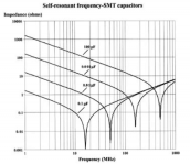
2. The self resonance of even small capacitors is well below typical RF radio frequencies so even 100nF is an inductor at FM radio frequencies, more so for say 1uF.
3. The RF impedance of a speaker cable can be very low making it impossible to "short" with a capacitor.
1. The Zobel network is there to stabilize CFP output stages and has almost nothing to do with RF interference.
2. The self resonance of even small capacitors is well below typical RF radio frequencies so even 100nF is an inductor at FM radio frequencies, more so for say 1uF.
3. The RF impedance of a speaker cable can be very low making it impossible to "short" with a capacitor.
Attachments
Last edited:
1. Indeed, that's precisely why you can better use Thiele's series filters instead of Zobel networks.
2. True but irrelevant; as long as the impedance is low enough, it doesn't matter whether it is capacitive, inductive or resistive.
3. Your plot shows 8 ohm at 1 GHz and less than 1 ohm at 100 MHz for sufficiently large-valued, small-size capacitors, while cable characteristic impedances are usually in the 50 ohm to 300 ohm range, so I think this statement is incorrect except when the cable happens to resonate at the interfering frequency.
By the way, 8 ohm at 1 GHz corresponds to about 1.3 nH and a common rule of thumb is that 1 mm of wire at a large distance from any ground plane is about 1 nH. Hence, those capacitors must be physically small and must be connected such that there is as little common wire as possible between the parts to the left and to the right of it.
Last edited:
- Home
- Amplifiers
- Solid State
- Load balance in simple long-tailed pair?