You will like it.
The first driver I designed was in 1997. And it was a Lowther copy. Similar design to what you are interested in here. 6.5 inch high frequency plug and a whizzer cone. It was also my first serious kick at a backloaded horn. I came to a few conclusions. I like classical music. Big Pipe Organ and all the way down to solo lute. So quite a range. This driver even though it was 113db/watt had to much intermodulation distortion to be acceptable.
Second thing was that I hated whizzer cones.
Third thing was making and implementing high frequency diffraction plugs. They have nothing to do with phase. These plugs are evil, evil little things that along with whizzer cones do nothing well and cause as many problems as they supposedly cure.
But. In listening it could make some decent music. And it was ok until you cranked it up a little to much.
As an exercise in seeing what you can build and how it sounds I would definitely go for it. As your last speaker. Nah!
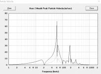
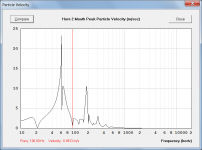
Here's something odd that I had happen, and I don't know if it is legit - changing between two similar woofers (the RS225P-4A and the RS225P-8A) changes the mouth velocity from ~1m/sec to like 5-6m/sec. Does this seem possible? The power response is otherwise quite similar.
No this makes no sense at all.
changing between two similar woofers (the RS225P-4A and the RS225P-8A) changes the mouth velocity from ~1m/sec to like 5-6m/sec. Does this seem possible? The power response is otherwise quite similar.
Although the power response shapes may be similar I think you will find that there is an approximate 3dB difference in absolute levels, for the same Eg input voltage. This is because Re = 3.30 ohms for the RS225P-4A driver and Re = 7.10 ohms for the RS225P-8A driver. The power output and diaphragm displacement (and therefore air particle velocity) will be greater for the RS225P-4A driver.
In simple terms:
Electrical input power = Eg ^ 2 / Re watts
RS225P-4A Electrical input power = 2.83 ^ 2 / 3.3 = 2.4 watts
RS225P-8A Electrical input power = 2.83 ^ 2 / 7.1 = 1.1 watts
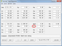
Fixed it--needed to check the Lossy Le box (I'd entered all those params previously for this driver).
Hi newracer,
It is very strange that not having the 'Lossy Le' check box selected should have generated a divide-by-zero error. When you say that you had "entered all those parameters previously for this driver" what parameters are you referring to?
Also, would it be possible to export and post a copy of the Hornresp record .txt file that caused the error, so that I can investigate further? Many thanks.
Kind regards,
David
[...] what parameters are you referring to?
Hi David,
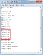
The params I was referring to were the semi-inductance params: Re', Leb, Le, Ke, and Rss.
Two export .txt files attached: debug1.txt is the one that crashes w/ the div-by-zero error; debug2.txt has one change and works: The Lossy Le box in the Wizard is checked. I notice now that if I switch the Lossy Le box back off, it still works. So it's only after I pasted my driver from the DB and then entered all Mark's horn and chamber parameters and Calculate that I get a crash.
Another thing I didn't mention in my earlier post: In the failing case, in the Loudspeaker Wizard, the main window in the Power screen had a red warning in the middle of the main chart viewport: "Fr1 is greater than zero", I think...I may be forgetting exactly what it said, but it was definitely about Fr1, and I remember that Fr1 *was* zero despite the warning.
Hope that helps! Let me know if I can provide anymore info...
Attachments
Last edited:
As an exercise in seeing what you can build and how it sounds I would definitely go for it. As your last speaker. Nah!
Hey Mark, great to read your perspective, and I checked out your website as well.
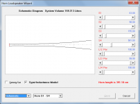
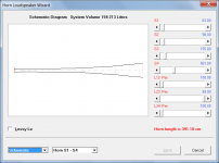
Attached is where I modified what you started with to get the attached result, so far anyway. While the volume of the whole system is now a little bigger than my previous design, and much bigger than your model's volume, the bass reaches down to 60Hz (vs. 100Hz in my design), so well worth it from that perspective. Basic changes are: added an FLH and accordingly had to combine the last two segments in the BLH into one to make input space, making the conflated segment exponential, which was the main trick for boosting low end SPL.
My only (not particularly well-informed) concerns at this point are the upper corner at only about 800Hz (which I'm not able to remedy thus far), and overall it's not quite as flat as my original design, though still very good, I think.
Attachments
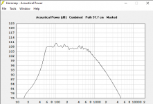
Although the power response shapes may be similar I think you will find that there is an approximate 3dB difference in absolute levels, for the same Eg input voltage. This is because Re = 3.30 ohms for the RS225P-4A driver and Re = 7.10 ohms for the RS225P-8A driver. The power output and diaphragm displacement (and therefore air particle velocity) will be greater for the RS225P-4A driver.
In simple terms:
Electrical input power = Eg ^ 2 / Re watts
RS225P-4A Electrical input power = 2.83 ^ 2 / 3.3 = 2.4 watts
RS225P-8A Electrical input power = 2.83 ^ 2 / 7.1 = 1.1 watts
David, that makes total sense, and after I posted it, I was wondering if this was the reason.
Hi newracer,
It does indeed!
Many thanks for your very comprehensive report, it has enabled me to work out exactly what is going on.
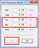
It seems that the semi-inductance parameter values must have been manually entered into the driver database text file. It is the only way that the Le and Ke values could be zero, and for the SemiInductance flag to be set, as shown in Attachment 1. If the semi-inductance advanced driver parameter values are entered via Hornresp then it is not possible to specify any of them as zero. The On button will be disabled if this is the case, as shown in Attachment 2.
The 'Division by zero' run-time error occurred because Hornresp needs to calculate the reactance value -1 / (2 * Pi * f * Le) and for your design, Le was zero.
Checking the Lossy Le box in the Wizard selects that option rather than the semi-inductance model, which is why the calculations then work. Switching the Lossy Le box back off does not automatically turn the semi-inductance model back on, so the calculations continue to work, with no option selected.
The message would have been "Fr1 is too large". The wizard contains a number of error trapping options. Division by zero triggered an error which is not specifically trapped because it should not normally occur. The error caused the Fr1 message to be displayed because it is the "catch-all" default when nothing else directly applies.
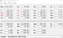
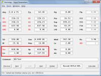
An indication that something is not quite right can be seen when the wizard is opened. Even though the Le label on the main input screen is coloured green indicating that the semi-inductance option has been selected, as shown in Attachment 3, the semi-inductance check box is not visible on the wizard, as shown in Attachment 4. It should be as shown in Attachment 5.
Thanks again for your help in getting to the bottom of this mystery. The take-away message for everyone is to enter advanced driver parameters via the appropriate input form 🙂.
Kind regards,
David
Hope that helps!
It does indeed!
Many thanks for your very comprehensive report, it has enabled me to work out exactly what is going on.
It seems that the semi-inductance parameter values must have been manually entered into the driver database text file. It is the only way that the Le and Ke values could be zero, and for the SemiInductance flag to be set, as shown in Attachment 1. If the semi-inductance advanced driver parameter values are entered via Hornresp then it is not possible to specify any of them as zero. The On button will be disabled if this is the case, as shown in Attachment 2.
The 'Division by zero' run-time error occurred because Hornresp needs to calculate the reactance value -1 / (2 * Pi * f * Le) and for your design, Le was zero.
debug1.txt is the one that crashes w/ the div-by-zero error; debug2.txt has one change and works: The Lossy Le box in the Wizard is checked. I notice now that if I switch the Lossy Le box back off, it still works.
Checking the Lossy Le box in the Wizard selects that option rather than the semi-inductance model, which is why the calculations then work. Switching the Lossy Le box back off does not automatically turn the semi-inductance model back on, so the calculations continue to work, with no option selected.
In the failing case, in the Loudspeaker Wizard, the main window in the Power screen had a red warning in the middle of the main chart viewport: "Fr1 is greater than zero"
The message would have been "Fr1 is too large". The wizard contains a number of error trapping options. Division by zero triggered an error which is not specifically trapped because it should not normally occur. The error caused the Fr1 message to be displayed because it is the "catch-all" default when nothing else directly applies.
An indication that something is not quite right can be seen when the wizard is opened. Even though the Le label on the main input screen is coloured green indicating that the semi-inductance option has been selected, as shown in Attachment 3, the semi-inductance check box is not visible on the wizard, as shown in Attachment 4. It should be as shown in Attachment 5.
Thanks again for your help in getting to the bottom of this mystery. The take-away message for everyone is to enter advanced driver parameters via the appropriate input form 🙂.
Kind regards,
David
Attachments

Last edited:
My only (not particularly well-informed) concerns at this point are the upper corner at only about 800Hz
The simulation shows the power response. The actual measured pressure response will take directivity effects into account, which are likely to extend the upper rolloff frequency somewhat. Not sure that the Lossy Le model is applicable to the driver you are using, though.
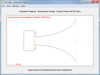
Is it possible to configure second segment of a horn as Tractrix? I able to define it only for first one. I would like to have first connical and second tractrix segment.
It seems that the semi-inductance parameter values must have been manually entered into the driver database text file. It is the only way that the Le and Ke values could be zero.
Hi David,
The values were entered via the form, which accepts values below "0.00", and it appeared to work at the time I entered them. The semi-inductance entries did raise SPL above 1kHz.
Is it possible that during the live session when the values were entered, Hornresp maintains and uses higher precision floating point values in RAM, but only writes two decimal places of precision in the DB?
Last edited:
Hi David, what's the possibility of the ability to model an offset driver in the rear chamber of the horn (FL, RL, etc.) ?
"Offset" meaning that the driver is not mounted directly facing the throat, but but on a cabinet wall adjacent to it. And yes, what I'm describing is different to an offset horn arrangement.. 🙂
"Offset" meaning that the driver is not mounted directly facing the throat, but but on a cabinet wall adjacent to it. And yes, what I'm describing is different to an offset horn arrangement.. 🙂
Hi David, I am also interested in the ability to set an offset on a rear chamber for an OD system or on horn 2 in a compound system. If it is possible the feature would definitely be put to good use 🙂
-John
-John
I have one other question regarding velocity on an OD model vs a CH model. There is a good delta between the models, which would be the most accurate?


Attachments

Is it possible to configure second segment of a horn as Tractrix?
No, but a throat adaptor can be included to effectively achieve the same outcome, as shown in the attachments.
Attachments

Is it possible that during the live session when the values were entered, Hornresp maintains and uses higher precision floating point values in RAM, but only writes two decimal places of precision in the DB?
Well done, you've nailed it!
Semi-inductance advanced parameter values less than 0.01 are being correctly saved to the main data file record, but not to the driver database record (where they are currently being rounded to two decimal places). This will be fixed in the next update. Values smaller than 0.01 will be formatted in scientific notation - similar to Cms and Ams.
Note that Leb can be zero if required.
Thanks again for your help in solving this puzzle.
Attachments

what's the possibility of the ability to model an offset driver in the rear chamber of the horn?
I am also interested in the ability to set an offset on a rear chamber for an OD system or on horn 2 in a compound system.
Hi Brian and John,
Sorry, it's not going to happen 🙂. The work involved would be horrendous - just think about the changes that would be required to the user interfaces to specify the offset conditions, particularly in the Loudspeaker Wizard - and that's before even starting on the modifications that would be necessary to the actual simulation models!
Things are complicated enough already 🙂.
Another one for AKABAK it seems...
Kind regards,
David
I have one other question regarding velocity on an OD model vs a CH model. There is a good delta between the models, which would be the most accurate?
There appears to be something wrong somewhere - the results should be effectively the same. I need to investigate further...
A number of problems identified in the Loudspeaker Wizard have now been fixed. Post #11581 refers.
Unfortunately another bug was introduced when attending to the above problems - it will be fixed in the next update.
In the meantime, some of the results with absorbent filling material added may be inaccurate.
There appears to be something wrong somewhere - the results should be effectively the same. I need to investigate further...
I have found the problem - it will be fixed in the next update.
For a perfectly accurate comparison the OD record should be changed as shown in Attachment 1, to make the simulation model identical to that of the CH1 record.
Vrc changed from 1.00 litre to 658.06 cc
Lpt changed from 128.91 cm to 127.91 cm
After the update the results will become identical, as shown in Attachments 2 and 3.
Attachments

- Home
- Loudspeakers
- Subwoofers
- Hornresp