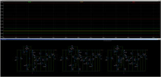
The circuit is still within the scope of this thread, since it uses a Xnoiser to improve a regulator.I have since improved it a bit. I used a cross between the nonoiser and dienoiser. I have also used some random led model I found, seems to perform worse than the ones in the library but seems to be having a closer Vdrop to the normal tht leds I have around.
Noise sim shows around 0.62nV/√Hz, PSRR around 120dB, and output impedance also dropped to around 0.5mOhm.
PSRR can be a bit higher with a LM329, or maybe a proper LED model. For the sim I used BD139 as pass transistor, I think it's a Bob Cordell model, around 100mA.
I tried to keep around 5mA going through the leds. To me the currents seem optimal, through the other components.
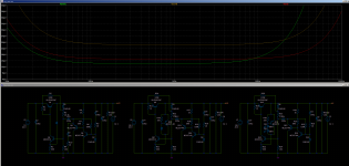
There's a delta of around 160mV between 25 and 75 degrees C for temperature sim.
Stepping the load between 10mA and 100mA there's a delta of around 120mV.
I guess figures could be improved a bit. I was in the middle of playing with the sim now. I pulsed the load and seems to recover nicely. I don't know if it needs compensation or ferrite bead like the NoNoiser.
I made a diy pcb of the previous version but I will do one for this version as well, seems like it should perform good. Considering the performance and price of components I think it's interesting.
The regulator itself (without the denoiser) is a bit strange though: it doesn't use negative feedback, the opposite in fact.
The reference is multiplied with the help of a bootstrap circuit, making it an amplified-zener regulator variant.
It works relatively well though, mostly thanks to the CCS, but it is probably possible to achieve better performance with an equivalent number of components by using NFB.
A possible example is this one:
Just for fun: a superreg with <12 discretes??! ?! ?
Without a xnoiser-like trick, it already vastly outperforms a 317 regulator, and with an additional 20~30dB improvement, its performances would become stellar
A possible example is this one:
Just for fun: a superreg with <12 discretes??! ?! ?
Without a xnoiser-like trick, it already vastly outperforms a 317 regulator, and with an additional 20~30dB improvement, its performances would become stellar
That's interesting and I'm going to play with it to understand it further.
I was just trying to make something that will work with the same type of bjt for small signal ones. I don't have small power fets and I don't know if I'll get any soon. What I made could be cobbled together with parts I already have. This was more of a curiosity, I'm really learning how the different blocks fit together and how they interact.
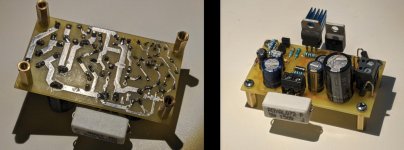
Managed to test the v1.3 tht diy single version board. Works fine. If you don't want to use the cap multiplier you can short pins 2 and 3 of the pass transistor with a wire link.
I used the same output voltage/current as the previous tests, around 11.25Vout and 75mA.
Input cap 470uF, output cap 100uF with 0.2R ESR. Compensation network 22nF + 5R or 47nF without R. I'd say to go for the 22nF/5R (4.7R, not critical value).
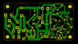
I made a few tweaks to the v1.3 design so I'll call this one v1.4, but the differences are really small, both designs should work the same. I added a sot-223 footprint in parallel with the LM317 to220 one so I can also play with sot223 compatible regs (LT3082) on this board. There's also an extra RLC network in parallel with the tht output cap, so you could use 1206 cap + 0805 inductor + 0805 resistor in case you want to experiment with ceramic cap on the output. For the measurements I sensed the noise on the output of the pcb, and LNA cable was soldered on the output connector. I added the design files for V1.4.
Simulation shows around 1.4Vdrop across the pass transistor and with 1.6Vdrop across the LM317 seems to work fine. So around 3Vdrop minimum from input to output.
I made the measurements for dienoiser, denoiser and simple lm317 without Cadj, as I didn't have a clean way to go from adj to gnd with the cap. I made these measurements for cap multiplier and without it also. I attached the measurements between all three versions with cap multiplier in a photo and without cap multiplier in the other. I also put all 6 measurements in a single photo. You can see how the cap multiplier lowers the ripple under the noise floor on any configuration.
So this version is tested if you want to make it. Works as expected.
edit: for cap multiplier I used MJE15032 + BC550C. There's a jumper for the tht output cap ESR correcting tht resistor, in case you use an output cap with the correct ESR range. There's also a jumper to switch from dienoiser to denoiser. And jumpers to sense on the output of the pcb instead of using coax for sense wires.
Board size remained the same 67mm x 37mm. It should be good for a max of 1.5A output just that you need to correctly size the input cap based on your conditions.
I used the same output voltage/current as the previous tests, around 11.25Vout and 75mA.
Input cap 470uF, output cap 100uF with 0.2R ESR. Compensation network 22nF + 5R or 47nF without R. I'd say to go for the 22nF/5R (4.7R, not critical value).
I made a few tweaks to the v1.3 design so I'll call this one v1.4, but the differences are really small, both designs should work the same. I added a sot-223 footprint in parallel with the LM317 to220 one so I can also play with sot223 compatible regs (LT3082) on this board. There's also an extra RLC network in parallel with the tht output cap, so you could use 1206 cap + 0805 inductor + 0805 resistor in case you want to experiment with ceramic cap on the output. For the measurements I sensed the noise on the output of the pcb, and LNA cable was soldered on the output connector. I added the design files for V1.4.
Simulation shows around 1.4Vdrop across the pass transistor and with 1.6Vdrop across the LM317 seems to work fine. So around 3Vdrop minimum from input to output.
I made the measurements for dienoiser, denoiser and simple lm317 without Cadj, as I didn't have a clean way to go from adj to gnd with the cap. I made these measurements for cap multiplier and without it also. I attached the measurements between all three versions with cap multiplier in a photo and without cap multiplier in the other. I also put all 6 measurements in a single photo. You can see how the cap multiplier lowers the ripple under the noise floor on any configuration.
So this version is tested if you want to make it. Works as expected.
edit: for cap multiplier I used MJE15032 + BC550C. There's a jumper for the tht output cap ESR correcting tht resistor, in case you use an output cap with the correct ESR range. There's also a jumper to switch from dienoiser to denoiser. And jumpers to sense on the output of the pcb instead of using coax for sense wires.
Board size remained the same 67mm x 37mm. It should be good for a max of 1.5A output just that you need to correctly size the input cap based on your conditions.
Attachments
-
 Screenshot from 2021-01-22 02-09-05.png355.4 KB · Views: 577
 -
 Screenshot from 2021-01-22 13-36-14.jpg107.9 KB · Views: 617
 -
 Screenshot from 2021-01-22 02-41-19.png59.3 KB · Views: 618
 -
 comp_no_cap_multi.png85.4 KB · Views: 594
 -
 comp_cap_multi.png89 KB · Views: 571
 -
 comparison.png111.1 KB · Views: 212
 -
single_diy_v1.4.zip180 KB · Views: 113
Last edited:
Those are really good graphs. Can I populate same board using same value components with LT1085? Not obvious from photos but there seems some smd components at bottom.
Last edited:
LT1085 works just that you can't use the full current output capabilities because of the bridge diodes and filter cap size.
The three smd components on the V1.4 are a RLC network for output cap. Instead of using a single THT output cap you can use a small 22uF ceramic + 30nH inductance + resistance depending on the type of regulator you use.
I will test some tht cap models with LT1085/LT3082 and post the results. Apart from the output cap, everything else could be the same for LT1085 as long as you don't go over 1.5A output.
For a 3A output board you should look at the v1.3 board for LT1085 from post #1889. But that is not tested and I don't think if or when I'll ever make it.
edit: compensation network might differ. I'd use 47nF or 68nF with 3.9R or 5R. I'll post the correct comp network once I test LT1085 on this board.
Last edited:
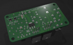
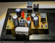
Since I made the V1.4 pcb I also made the pcb for the discrete regulator as I was curious to test it.
I used BC550+MJE15032 for cap multiplier and MJE15032 for pass transistor. Every other bjt is BC337/BC327. The LEDs are some random red LEDs I found in the LED box. Capacitors are all random ones, I only cared about capacitance values. The only difference is the denoiser coupling cap, it's 330uF instead of the 220uF from the schematic. And the output cap is 220uF.
Seems to be working just like the simulation predicted. The noise floor seems a bit lower than LM317+dienoiser.
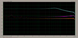
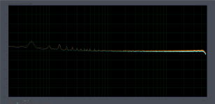
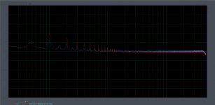
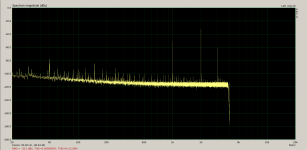
First photo is a comparison between LM317+dienoiser (orange trace) and discrete (cyan trace) both with cap multiplier in circuit.
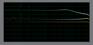
Second photo is a comparison between the discrete with cap multiplier in circuit (cyan trace) and discrete with cap multiplier shorted (red trace).
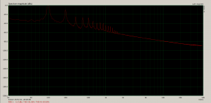
Third photo is the simple discrete regulator by itself without the denoiser and with cap multiplier shorted. It goes a bit over 0dB, around +0.5dB or so.
Noise measurements were done with 60dB LNA.
I will try some other LED colors and I also have a LM329 and some random Zeners.
The output voltage is around 0.15V higher than simulation, but 0.1V is because of the LEDs, which simulated with a bit lower Vdrop.
edit: I poked at the various denoiser nodes with metal tweezers and it seemed to recover very fast, just a blip on the noise live measurement graph. I didn't use compensation. Same conditions as LM317 + dienoiser, 11.25Vout and around 75mA current draw.
I used BC550+MJE15032 for cap multiplier and MJE15032 for pass transistor. Every other bjt is BC337/BC327. The LEDs are some random red LEDs I found in the LED box. Capacitors are all random ones, I only cared about capacitance values. The only difference is the denoiser coupling cap, it's 330uF instead of the 220uF from the schematic. And the output cap is 220uF.
Seems to be working just like the simulation predicted. The noise floor seems a bit lower than LM317+dienoiser.
First photo is a comparison between LM317+dienoiser (orange trace) and discrete (cyan trace) both with cap multiplier in circuit.
Second photo is a comparison between the discrete with cap multiplier in circuit (cyan trace) and discrete with cap multiplier shorted (red trace).
Third photo is the simple discrete regulator by itself without the denoiser and with cap multiplier shorted. It goes a bit over 0dB, around +0.5dB or so.
Noise measurements were done with 60dB LNA.
I will try some other LED colors and I also have a LM329 and some random Zeners.
The output voltage is around 0.15V higher than simulation, but 0.1V is because of the LEDs, which simulated with a bit lower Vdrop.
edit: I poked at the various denoiser nodes with metal tweezers and it seemed to recover very fast, just a blip on the noise live measurement graph. I didn't use compensation. Same conditions as LM317 + dienoiser, 11.25Vout and around 75mA current draw.
Attachments
Last edited:
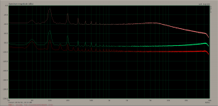
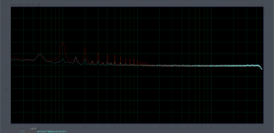
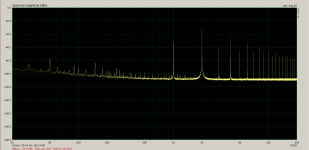
And also a comparison between LM317+dienoiser and the discrete without capacitance multiplier on both. LM317+dienoiser has a better PSRR at 100Hz, by about 15dB. But the discrete has a bit lower noisefloor. Red trace is the discrete regulator.
Attachments
I tested the discrete pcb with various LEDs and LM329. The LM329 version had a higher psrr (closer to LM317+dienoiser than the LED version) but a bit worse noisefloor, but by very little. I tried a few models for yellow, orange, red and IR LEDs. All showed similar performance for what I can measure. I settled for two types of LEDs on the final version, both IR. For the CCS I used a lower wavelength LED, as it was useful to see a bit of light to know if the supply is on or off. For the voltage reference I used higher wavelength IR versions (lower Vdrop). You could use either IR-red-orange-yellow LEDs for similar performance overall. I think I gained a few dB in PSRR with the IR versions but I don't know if it's because of the LEDs or the other values I changed to accommodate them into the circuit. IR LEDs help if you don't like light coming out of your pcbs.
Figured I should test the supplies with an amplifier load. I used a TDA7297 with a 4ohm resistor load. Same Vout/Aout for both LM317+dienoiser and discrete+denoiser boards, around 11.4V and 70-100mA. The amp draws around 40mA at idle.
Noticed that increasing the FFT resolution I get better defined signals, and also changing the sample rate allows me to "see" deeper into the noisefloor. The lower the sample rate the lower I can see, but it cuts into the maximum frequency I can see. The lowest I can go from ARTA is 8kHz, which lets me see to about 3.8kHz or so. The downside is that at 8kHz with full FFT resolution it takes a really long time for each sample.
I used 1kHz signal, and curious that I see 2nd harmonic higher than the fundamental. The second harmonic goes past the fundamental early into increasing the signal. At first it's lower but goes higher a few volume steps in. There seems to be even harmonics predominating for LM317+dienoiser, simple LM317 without dienoiser or Cadj, and also for the discrete regulator.
For the same audio signal the fundamental+harmonics of discrete version are a few dB higher. I presume this is because of the slightly increased output impedance? The discrete version is still very low, just that not really at the LM317+dienoiser level. In practice it shouldn't matter at all, it was just an observation.
From the attached graphs to me it seems that both regulator versions behave very similarly. I tried sine, square, triangle and saw tooth on both and they behaved the same, no issues. I ran sweeps and both seemed to have lower fundamental+harmonics towards the higher end of the audio spectrum, but by few dB, barely noticeable. I tried two different phones for signal source and results were identical.
I used the 60dB LNA for all measurements, and I sensed the supplies output at the output connector. There's some length of trace between each regulator output and output connector but it's not that long and I also made them thicker with solder. I'm not sure how much they contribute to the output impedance or if they drown the differences between the LM317+dienoiser and discrete version.
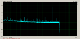
First photo is LM317+dienoiser pcb with a total of around 80-100mA load from the amp, 1kHz signal and 44.1kHz sample rate. Second photo is same thing but for the discrete pcb. Third is a comparison between the two.
Fourth photo is LM317+dienoiser pcb with same conditions but 8kHz sample rate. Fifth photo the same but for the discrete pcb.
The sixth photo is of a comparison between both regulators with 150R load at around 75mA at 44.1kHz sample rate, shows a bit more in the noise floor than previous measurements.
The last photo is of LM317 normal setup without the dienoiser or Cadj, amp as load at 8kHz sample rate.
In all tests both regulator pcbs had the capacitance multiplier in circuit.
LM317 trace is yellow and discrete is cyan.
Figured I should test the supplies with an amplifier load. I used a TDA7297 with a 4ohm resistor load. Same Vout/Aout for both LM317+dienoiser and discrete+denoiser boards, around 11.4V and 70-100mA. The amp draws around 40mA at idle.
Noticed that increasing the FFT resolution I get better defined signals, and also changing the sample rate allows me to "see" deeper into the noisefloor. The lower the sample rate the lower I can see, but it cuts into the maximum frequency I can see. The lowest I can go from ARTA is 8kHz, which lets me see to about 3.8kHz or so. The downside is that at 8kHz with full FFT resolution it takes a really long time for each sample.
I used 1kHz signal, and curious that I see 2nd harmonic higher than the fundamental. The second harmonic goes past the fundamental early into increasing the signal. At first it's lower but goes higher a few volume steps in. There seems to be even harmonics predominating for LM317+dienoiser, simple LM317 without dienoiser or Cadj, and also for the discrete regulator.
For the same audio signal the fundamental+harmonics of discrete version are a few dB higher. I presume this is because of the slightly increased output impedance? The discrete version is still very low, just that not really at the LM317+dienoiser level. In practice it shouldn't matter at all, it was just an observation.
From the attached graphs to me it seems that both regulator versions behave very similarly. I tried sine, square, triangle and saw tooth on both and they behaved the same, no issues. I ran sweeps and both seemed to have lower fundamental+harmonics towards the higher end of the audio spectrum, but by few dB, barely noticeable. I tried two different phones for signal source and results were identical.
I used the 60dB LNA for all measurements, and I sensed the supplies output at the output connector. There's some length of trace between each regulator output and output connector but it's not that long and I also made them thicker with solder. I'm not sure how much they contribute to the output impedance or if they drown the differences between the LM317+dienoiser and discrete version.
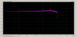
First photo is LM317+dienoiser pcb with a total of around 80-100mA load from the amp, 1kHz signal and 44.1kHz sample rate. Second photo is same thing but for the discrete pcb. Third is a comparison between the two.
Fourth photo is LM317+dienoiser pcb with same conditions but 8kHz sample rate. Fifth photo the same but for the discrete pcb.
The sixth photo is of a comparison between both regulators with 150R load at around 75mA at 44.1kHz sample rate, shows a bit more in the noise floor than previous measurements.
The last photo is of LM317 normal setup without the dienoiser or Cadj, amp as load at 8kHz sample rate.
In all tests both regulator pcbs had the capacitance multiplier in circuit.
LM317 trace is yellow and discrete is cyan.
Attachments
-
 discrete_load_1khz_8khz_sample.png61.3 KB · Views: 95
 -
 lm317_load_1khz_8khz_sample.png61.6 KB · Views: 97
 -
 lm317_vs_discrete_load_comparison_1khz_44.1khz_sample.png78.1 KB · Views: 100
 -
 discrete_load_1khz_44.1khz_sample.png61.8 KB · Views: 101
 -
 lm317_load_1khz_44.1khz_sample.png62.5 KB · Views: 120
 -
 lm317_vs_discrete_44.1khz_150R_load.png77.4 KB · Views: 99
 -
 lm317_normal_1khz_8k_sample.png60.1 KB · Views: 98
Last edited:
After talking with Carlos and checking the discrete version from his thread, I decided to try and adapt the denoiser to that circuit as well.
For the same output conditions the performance of this new variant seems to be superior. You can have extra performance gains by using a LM329 instead of the GLED setup, I think some dB for PSRR.
The output impedance is also even lower with this version. And I think there's one less transistor than the previous version, but this one uses a PNP pass transistor.
Temperature sim is not great, I think it might be better with LM329, I didn't try with that yet.
For some reason the temp sim fails on the highest temp for some BJT used in GLED setup.
Also 2N5551 seems to be giving very good performance in this circuit. What is special about it that makes it good in that position?
edit: added LM329
Attachments

Last edited:
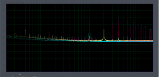
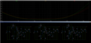
With LM329 inside the GLED setup it seems to have the best tempco. I attached the PSRR, output impedance and tempco for all versions.
Attachments
The 5551 model probably has a higher Vaf, or a Vaf that nicely compensates for something else.Also 2N5551 seems to be giving very good performance in this circuit. What is special about it that makes it good in that position?
edit: added LM329
You can play with Vaf in the model, and possibly add a cascode stage to eliminate the effect.
You have two very different breeds of regulators in your lineup: the third one is unconventional (certainly not a bad thing), but since it doesn't rely on NFB, it requires a highish standing current and an additional transistor to achieve good performances.
It also requires a low impedance divider, meaning a large coupling capacitor to the Xnoiser.
VAF....Just in case.
Beware of Spice simulations using default BJTs, those have infinite VAF.
Beware of Spice simulations using default BJTs, those have infinite VAF.
The 5551 model probably has a higher Vaf, or a Vaf that nicely compensates for something else.
You can play with Vaf in the model, and possibly add a cascode stage to eliminate the effect.
You have two very different breeds of regulators in your lineup: the third one is unconventional (certainly not a bad thing), but since it doesn't rely on NFB, it requires a highish standing current and an additional transistor to achieve good performances.
It also requires a low impedance divider, meaning a large coupling capacitor to the Xnoiser.
Thank you for the info! Yes the coupling capacitor value is not adjusted to that resistor. I think the corner frequency should be 0.1Hz?
VAF....Just in case.
Beware of Spice simulations using default BJTs, those have infinite VAF.
I think I used Bob Cordell's models but I have to check to make sure. Are those more defined than the stock models?
I remember testing KSC2690 in that spot and performed similarly good to 2N5551.
There is no compulsory corner frequency: it can be as low as you like (if you tolerate the large cap and long settling time), and it can be raised if you don't need VLF performance. 0.1Hz is a reasonable tradeoff, as it will give around 40dB correction @100Hz.Thank you for the info! Yes the coupling capacitor value is not adjusted to that resistor. I think the corner frequency should be 0.1Hz?
The dienoiser should have a correction gain somewhat higher than 40dB, thus if you want to use its full 100Hz rejection capability, you should aim for a lower Fc.
When selecting the coupling caps, you need to keep the input and output poles sufficiently apart, otherwise VLF peaking will occur.
Regarding Vaf, the values provided in the models, even the Cordell ones, should be taken with a pinch of salt: Vaf is a convenient theoretical concept, almost a happy mathematical convergence, but the physical reality diverges significantly and the actual value varies depending on the conditions.
In addition, the value can differ significantly from the published model: modern transistors, even cheap generic ones from Chinese origin tend to have a much higher Vaf than earlier types but the models are rarely updated
I built the nfb version but it's not stable. Tried also with only one transistor like the normal denoiser but still I couldn't make it stable. The positive feedback version was stable without any compensation or special output capacitor.
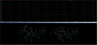
Looking at the sim I noticed that the NFB version has more self-noise attenuation. If I can get it stable it should have a lower noise floor than any other regulator I measured so far.
I attached a photo with noise reduction sim for both designs.
Looking at the sim I noticed that the NFB version has more self-noise attenuation. If I can get it stable it should have a lower noise floor than any other regulator I measured so far.
I attached a photo with noise reduction sim for both designs.
Attachments
Elvee, any idea why the circuit on the left is not working with the denoiser but the one on the right (which I made and measured fine) is working with the denoiser? I simplified the reference without the GLED setup for simplicity. But the GLED helps with tempco and also with driving the pass transistor harder for higher output current without affecting the reference.
It might be related to why the latest version I made is not stable.
The PSRR is similar between them, output impedance is lower for the circuit on the left, but the big difference is in self-noise reduction. The one on the left already has a good 50dB or so without de denoiser, on top of which the denoiser adds another 60dB or so. I suspect this high reduction in self-noise is what is making it unstable. Both are set for similar output voltage.
Can it somehow be stabilized?
edit: I am interested in getting the high self-noise reduction (edit: -125dB or so in audio band for the circuit on the left with the denoiser! and -130dB with the GLED setup). I could deal with PSRR with a cap multiplier.
Also using ZTX851/951 for everything on the circuit on the left shows around 620pV/√Hz for the .noise sim. Which I don't really understand how is related to self-noise and noise floor.
Attachments

Last edited:
The loop gain is obviously much higher, which explains the higher perf, but also the difficulty to stabilize it.I built the nfb version but it's not stable. Tried also with only one transistor like the normal denoiser but still I couldn't make it stable. The positive feedback version was stable without any compensation or special output capacitor.
Looking at the sim I noticed that the NFB version has more self-noise attenuation. If I can get it stable it should have a lower noise floor than any other regulator I measured so far.
I attached a photo with noise reduction sim for both designs.
A proper loop analysis would be required to fix it
The circuit on the left has an opposite polarity, meaning it also requires an inverted Xnoiser, PNP-->NPN and NPN-->PNP.Elvee, any idea why the circuit on the left is not working with the denoiser but the one on the right (which I made and measured fine) is working with the denoiser?
This will solve the multivibrator behaviour, but the loop gain might also be too high
I tried swapping the transistors in the denoiser but now the denoiser is degrading the regulator performance.
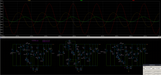
I wanted to check the phase between the three versions. In the picture attached, the one on the right is the positive feedback one that is working fine, the one in the middle is the latest one I built that I couldn't yet make stable, the one on the left is the one on the left in the previous post/photo.
Looking at their phase (as the signal comes out of the denoiser), the one in the center and right are somewhat in phase, but the one on the left is 90 degrees off. Could this be the issue? When connected as in the previous post it's 180 degrees out of phase with the ones in the center and the one on the right in this photo.
edit: and while the center and right regulators have their denoiser output 180 degrees out of phase with their output ac signal, the one on the left has it in phase with the signal on its output with the denoiser transistors swapped.
Attachments
Last edited:
All of this needs to be examined and analysed calmly, with a cool head.
The first thing to do is to get the basic polarity right, then to address the loop stability issues.
Tradeoffs and response shaping will probably be needed, due to the high gain available.
Presently, I have my mind busy with a number of totally unrelated, unpleasant problems, and I have no time to delve into the fine details of this issue.
In some weeks or months, all of that should be behind me, and I'll be able to analyse the problem in a cool, systematic and collected way, but for the moment I can just hint at what needs to be done.
- Home
- Amplifiers
- Power Supplies
- D-Noizator: a magic active noise canceller to retrofit & upgrade any 317-based VReg