Yes very-very good service!!!Thanks Thimios,
only 4 business days to Greece economy post, Deutsche Post / DHL is always good for surprises. Be aware of the modifications of the drillings, i mentioned in the PMs
Günni
Don't worry,i will modify parts pins when they can't feet.😉
Thanks for your offer!
Regards.
Thimios
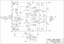
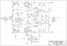
It is not necessary to change anything on the pcb, just some resistors values.
R6 and R9 change to 11k and instead of R5 and R10 just use a jumpers.
Hello Damir,
are those changes also valid for the Class A version?
Günni
Hello Damir,
are those changes also valid for the Class A version?
Günni
Gunni, try it as original schematic, but without VAS emitter caps, and if no oscillation try with caps.
As youknow the amp I tested was with CCS in theinput, this one is with simple resistors.
Damir
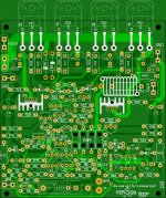
a few mechanical issues
Hello Damir,
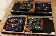
since i am close to finish one pair of each version, i want report some remarks egarding mechanical issues:
all drillng holes for R >1W very tight, the same for C1,C8,C11
drillling holes for Q9 and Q10 too tight (2SA1381,2SC3503)
the source resistors R37 and R38 are very close to the capacitors (Lifetime vs temperature)
for C20 i used a MKP2 from Wima with 100nF 100V (5mm x7mm base area)
the area C19, C20 R40 R39 hard to equip, since R39 overlaps R40 (left drill hole of R40 too small), to prevent stress, i equipped R40 from the bottom side.
Waiting for 1 resitor value and winding the coils, and the ready to turn on. Let's hope the best.
Günni
Hello Damir,
since i am close to finish one pair of each version, i want report some remarks egarding mechanical issues:
all drillng holes for R >1W very tight, the same for C1,C8,C11
drillling holes for Q9 and Q10 too tight (2SA1381,2SC3503)
the source resistors R37 and R38 are very close to the capacitors (Lifetime vs temperature)
for C20 i used a MKP2 from Wima with 100nF 100V (5mm x7mm base area)
the area C19, C20 R40 R39 hard to equip, since R39 overlaps R40 (left drill hole of R40 too small), to prevent stress, i equipped R40 from the bottom side.
Waiting for 1 resitor value and winding the coils, and the ready to turn on. Let's hope the best.
Günni
I am back home next week and I will see to the pcb layout.
Hope for best.
Damir

Hello Damir,
since i am close to finish one pair of each version, i want report some remarks egarding mechanical issues:
all drillng holes for R >1W very tight, the same for C1,C8,C11
drillling holes for Q9 and Q10 too tight (2SA1381,2SC3503)
the source resistors R37 and R38 are very close to the capacitors (Lifetime vs temperature)
for C20 i used a MKP2 from Wima with 100nF 100V (5mm x7mm base area)
the area C19, C20 R40 R39 hard to equip, since R39 overlaps R40 (left drill hole of R40 too small), to prevent stress, i equipped R40 from the bottom side.
Waiting for 1 resitor value and winding the coils, and the ready to turn on. Let's hope the best.
Günni
Hi Gunni,
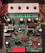
After long time😱 I have one more build result here from Croatia.
Here is improved PCB board gerebers.
I followed your suggestion about layout and did some more ugrade, actually just increase in value for R11 and R12 to 22k and add caps C5 C27 to prevent coscode oscilation.
Still is possible to use old PCB with some careful increasing some to small holes.
Capacitors parallel to VAS resistors are removed.
Output mosfet source resistor can have different (smaller value) or not used at all(short jumpers) if output mosfet well matched.
BR Damir
Attachments
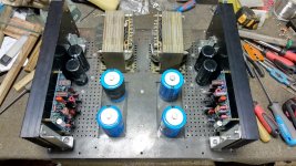

After some listening, amp started to have distorted sound. I've spend a few days to track down the problem and the problem was RF noise no being decoupled to GND. Solution was 10nF ceramic caps from input RCA GND to chassis.
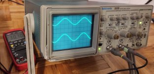
After that, amp sounded great, but on some specific frequencies it sounded weird. I have measured it with Tektronix 2225 and everything was fine. That, I've decided to measure it on Tektronix TAS250, just to be sure and saw oscillation. 😕 Guess my 2225 needs some refresh and calibration.
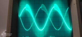
Oscillation occured only above +-50V. On the attached picture, it was +-50.3V. On +-55V, sine wave wasn't recognizable. But how? Amp works and sounds good.
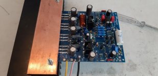
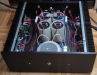
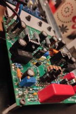
I started to track down the problem and solution was to tighten the Exicon laterals with aluminium profile on the Exicons (see picture). The key is that everything needs to have a good GND connection. After that, oscillations were there, but they were reduced. Next thing was to change gate stoppers from 270R/330R to 560R/680R. After that, no oscillation occured even on +-60V.
And last thing, 1uF caps C8/C11, bypass caps on VAS, with this modifications can be used with no oscillation. They were never the problem, problem were Exicon mosfets.
So, if you want to build this amp and use PSU over +-50V you need to make this mods, but on +-45V (safe margin from +-50) it is good to go with original schematic from post #1.
Good day to you all.
After that, amp sounded great, but on some specific frequencies it sounded weird. I have measured it with Tektronix 2225 and everything was fine. That, I've decided to measure it on Tektronix TAS250, just to be sure and saw oscillation. 😕 Guess my 2225 needs some refresh and calibration.
Oscillation occured only above +-50V. On the attached picture, it was +-50.3V. On +-55V, sine wave wasn't recognizable. But how? Amp works and sounds good.
I started to track down the problem and solution was to tighten the Exicon laterals with aluminium profile on the Exicons (see picture). The key is that everything needs to have a good GND connection. After that, oscillations were there, but they were reduced. Next thing was to change gate stoppers from 270R/330R to 560R/680R. After that, no oscillation occured even on +-60V.
And last thing, 1uF caps C8/C11, bypass caps on VAS, with this modifications can be used with no oscillation. They were never the problem, problem were Exicon mosfets.
So, if you want to build this amp and use PSU over +-50V you need to make this mods, but on +-45V (safe margin from +-50) it is good to go with original schematic from post #1.
Good day to you all.
Attachments


Forgot to mention, dadod was very helpful with solving this issues. Ilimzn to and Gaso (don't know if he is a member here).
I did not built this amp with Exicon laterals but with Hitachi ones in TO-3 case, and there was not oscillation problem. When Filkoman said to me that oscilation stops when Exicon case touched by hand, I suspected stray capacitances and non metal case of those laterals. Metal grounded cover over plastic laterals solved the problem plus increaded value of the gate stoppers.
Why before it was not distorting?after some listening, amp started to have distorted sound
+/-50V /8 ohm =156w rms. Do you listen so loud?
120w CFA.
Why before it was not distorting?
+/-50V /8 ohm =156w rms. Do you listen so loud?
120w CFA.
Check you math, it would be closer to 90w assuming 70% efficiency
- Home
- Amplifiers
- Solid State
- Lateral CFA 120W - BSA