Went DC or hit the rails? These things are such a challenge to bias, when you finally learn how it's satisfying.
When I start with an amp like this I use a little resistive padding here and there, just in case.
When I start with an amp like this I use a little resistive padding here and there, just in case.
Hit the rails as I remember. Full rail voltage of one side thru the voice coil. Didn't hear it happen, it was that way for hours.
We only need eduard barcching in here telling him he just need to add lundahl chokes🙂
Hello,
No need to that my stock of Lundahl high current choke is gone.
Hiraga first published about the 20 watt Hiraga in 1979. A few years later they found some power transistors that allowed them to make a 30 watt too.
In 1983 he published the first article about '' le Monstre '' 8 watt . A few years ago someone started selling a heavenly pimped monster with more power.
In this short thread people are already mixing up these different creatures. If you consider as a monstrous animal you should indeed make a chassis construction with some wood!
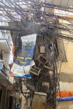
The wiring reminds me of my holidays in Vietnam.
Greetings, Eduard
Attachments
A bigger FB R means less general feedback if I am right...
Closed loop amplification = feedback resistor / ground resistor +1
Au = (Rf / Rg) + 1
or
Au = (Rf + Rg) / Rg
So a higher feedback resistor yields a higher overal closed loop amplification.
Why the oscillation?
In the upper band with a reduced closed loop gain it is possible 'peaking' may occur. All depending on internal phase shift by parasatic capacitances and miller effects in the amplifier stages. When the total phase shift is nearing 180° (from above 135° onwards) at these high frequencies, the loop gain forces the amp to oscillate.
Increasing this loop gain lifts the overall gain above the peaking level so the oscillation stops. Or one can reduce the loop gain at these high frequencies by adding a feedback capacitance parallel over the feedback resistor to force a lower loop gain there and supressing any oscillation. A drawback is a reduced bandwith (the Bode-plot). And there lies the magic of a good design, to name one parameter.
Currently I'm designing (and building already) a balanced bridge Hiraga (no two amps, but a single with two balanced outputs). Without the offset pot - not needed anymore. It consists of two (balanced bridged) legs (1943/5200) at 1A, as a poc for a four-legged one.You're lucky! The first one I built (from the Audiophile kit) went DC and killed a JBL woofer. My fault, I had used a transformer slightly higher voltage and maybe didn't compensate on the bias. Blew the output transistors, likely from over heating. 🙁
I had some more of this trouble.
Not completely solved.
After I turned the volume way down for silence, when I turned it back up the right channel was gone. Old issue. I reset the amp , all fine again.
I think the less feedback has helped, and it sounds nicer 🙂
But more work required.
I’ll try the cap bypass on the FB Res.
If it degrades the sound I might try pf caps Base Collector on the driver transistors instead of.
From all comments I get on this thread,
1. the driver trannies behind the power trannies are susceptible to the problem.
2. Adding capacitance to the BC may alter phase shifts enough to cure it.
Have I got that right?
Many thanks,
Pauly.
Closed loop amplification = feedback resistor / ground resistor +1
Au = (Rf / Rg) + 1
or
Au = (Rf + Rg) / Rg
So a higher feedback resistor yields a higher overal closed loop amplification.
Why the oscillation?
In the upper band with a reduced closed loop gain it is possible 'peaking' may occur. All depending on internal phase shift by parasatic capacitances and miller effects in the amplifier stages. When the total phase shift is nearing 180° (from above 135° onwards) at these high frequencies, the loop gain forces the amp to oscillate.
Increasing this loop gain lifts the overall gain above the peaking level so the oscillation stops. Or one can reduce the loop gain at these high frequencies by adding a feedback capacitance parallel over the feedback resistor to force a lower loop gain there and supressing any oscillation. A drawback is a reduced bandwith (the Bode-plot). And there lies the magic of a good design, to name one parameter.
Very strange behaviour, I would investigate it some more, when resetting, do you just flip the switch or does it have to cool down?
Doesn’t have to cool down.
Procedure I do to reset is detailed earlier in thread.
All solder joints checked and Re flow’d.
It’s definitely simply unstable in one channel.
I have 3n9 caps on the FB R’s now.
Just evaluating... 😉 .
Thanks,
P.
Procedure I do to reset is detailed earlier in thread.
All solder joints checked and Re flow’d.
It’s definitely simply unstable in one channel.
I have 3n9 caps on the FB R’s now.
Just evaluating... 😉 .
Thanks,
P.
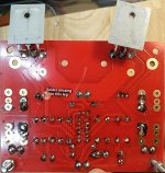
That joint does look pretty crap in that photo.
But I swear I checked all solder joints. Re flowed them too.
Will have another look next time I have the board out.
Thanks,
P.
But I swear I checked all solder joints. Re flowed them too.
Will have another look next time I have the board out.
Thanks,
P.
I think you have some faulty transistor or broken pin, drivers at +/- 23V are the first in danger, I would go for something stronger in TO126, 300R resistor (220R in the original) in the feedback must be 1W.
I would definitely check all the solder joints when I see that picture above.
pauly99 can you measure currents through input jfet and output on both channels? and voltages would be good to measure especially when the amplifier goes into error
I would definitely check all the solder joints when I see that picture above.
pauly99 can you measure currents through input jfet and output on both channels? and voltages would be good to measure especially when the amplifier goes into error
Attachments
I'll be interested to see what you come up with.Currently I'm designing (and building already) a balanced bridge Hiraga (no two amps, but a single with two balanced outputs).

I think you have some faulty transistor or broken pin, drivers at +/- 23V are the first in danger, I would go for something stronger in TO126, 300R resistor (220R in the original) in the feedback must be 1W.
I would definitely check all the solder joints when I see that picture above.
pauly99 can you measure currents through input jfet and output on both channels? and voltages would be good to measure especially when the amplifier goes into error
Hi Grunf,
Which transistor do you recommend upgrade for to TO126?
What voltage do you measure at the junction of the 2 Fet Source R’s?
( i strongly doubt 1W FB R is needed )
My solder joints are filthy and need a clean but as I’ve said ALL are good.
I think measuring the DC voltages around the circuit is a good suggestion.
I think putting a scope on to prove the presence of oscillations is also good.
Aside I have increased FB R , AND a bypass cap of 3n9.
I think it STILL has the problem. Other board is faultless ! Amazing.
There has to be a fault with some transistor on the bad board.
Hopefully DC conditions will reveal something.
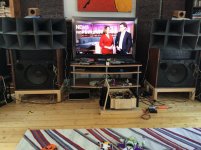
Despite all this the amp sounds positively glorious. Amazing.
I have a pretty good tube amp, ( feral eye like ) that has been in the
Cupboard for a year since the Hiraga came along 🙂
Pauly.
Here is some aside info.
I like the sound of the bigger FB R, as said.
Interesting is the effect of the bypass cap, 3n9.
At first I didn’t like it. I heard loss in the top.
Kind of a bit less decay in upper treble.
I resigned to remove these caps the next day.
But as I listened for the rest of last night, I thought, something sounding good there.
Today I A,B,A tested with and without the cap.
Result: I actually prefer the cap in! Wow. I might not prefer that top decay, which now sounds like it may be distortion, and the mids , presence and Pratt and transparency? is better. Probably going to leave it in for sound reasons.
I thought I’d mention this because obviously people are interested in the hiraga here...
Attachments
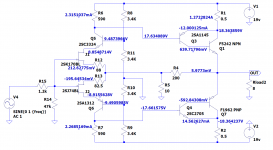
As said in #50 ("300Ω and 3n9 in parallel yields 136kHz"), the phase starts to roll from 13.6kHz onwards (I always take one decade).
Try 3.3 - 2.7 - 2.2 - 1.5n (or 2 x 3.9 in series ~ 2n) to lift it a bit higher.
From 2.7 above 20kHz.
Try 3.3 - 2.7 - 2.2 - 1.5n (or 2 x 3.9 in series ~ 2n) to lift it a bit higher.
From 2.7 above 20kHz.
Heat issue.
Background to question:
One thing I forgot was that the change of FB effects the DC conditions as well as AC. Idle current was up to 2.5A. I readjusted the bias, now is 1.7A.
But I have noticed that as it heats up the current rises to 2A.
If I take the lid off the amp it returns to normal.
I gather it’s the heat that creates some sort of thermal runaway?
Is this normal?
Is this the point at which fans become necessary on ClassA amps?
Thanks,
Paul.
At that current expect a high level of thermal distortion and low bandwidth. Heat can permanently alter the constitution of a transistor.
Again, PSRR is principally a matter of topology not supply voltage.
Again, PSRR is principally a matter of topology not supply voltage.
- Home
- Amplifiers
- Solid State
- Problem with an Hiraga amp.